|
1
|
INSPECT BATTERY
• Refer to the battery inspection and inspect the battery.
• Is the battery normal?
|
Yes
|
Go to the next step.
|
|
No
|
Replace or charge the battery.
Go to Step 5.
|
|
2
|
INSPECT FUSE
• Switch the ignition to LOCK.
• Disconnect the negative battery cable and wait 1 min or more.
• Remove the ENGINE 15 A fuse.
• Is the fuse normal?
|
Yes
|
After installing the ENGINE 15 A fuse, go to the next step.
|
|
No
|
Replace the ENGINE 15 A fuse.
Go to Step 5.
|
|
3
|
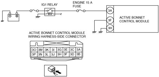
INSPECT WIRING HARNESS BETWEEN ACTIVE BONNET CONTROL MODULE AND IG1 RELAY
-
Warning
-
• Handling the component parts improperly can accidentally operate the active bonnet actuator, which may seriously injure you. Read the service warnings and cautions before handling the component parts of the active bonnet.
• Disconnect the active bonnet actuator (RH, LH) connector.
• Remove the partition board.
• Remove the trunk side trim (RH).
• Disconnect all of the active bonnet control module connectors.
• Connect the negative battery cable.
• Switch the ignition ON.
• Measure the voltage of the active bonnet control module terminal 3A (wiring harness side).
-
Note
-
• Measure the voltage while shaking the wiring harness between the active bonnet control module and the IG1 relay.
• Is the voltage between 8―17.9 V?
|
Yes
|
Go to the next step.
|
|
No
|
Replace the wiring harness between the active bonnet control module and the IG1 relay.
Go to Step 5.
|
|
4
|
INSPECT ACTIVE BONNET CONTROL MODULE (RIGHT) CIRCUIT FOR OPEN CIRCUIT
• Verify that the active bonnet control module connector is disconnected.
• Switch the ignition to LOCK.
• Disconnect the negative battery cable and wait 1 min or more.
• Inspect for continuity between the following terminals (vehicle wiring harness side) and body ground.
-
― Active bonnet control module terminal 3F
― Active bonnet control module terminal 3H
-
Note
-
• Inspect for continuity while shaking the wiring harness between the active bonnet control module and body ground.
• Is there continuity?
|
Yes
|
Go to the next step.
|
|
No
|
Replace the wiring harness, then go to the next step.
|
|
5
|
PERFORM DTC INSPECTION FOR ACTIVE BONNET CONTROL MODULE
• Connect the active bonnet control module connector.
• Reconnect all the disconnected connectors.
• Connect the negative battery cable.
• Switch the ignition ON.
• Clear the DTC for the active bonnet control module using the M-MDS.
• Perform the active bonnet control module DTC inspection using the M-MDS.
• Is the same DTC displayed?
|
Yes
|
Replace the active bonnet control module.
|
|
No
|
DTC troubleshooting completed.
|