 |
am2zzw00014577
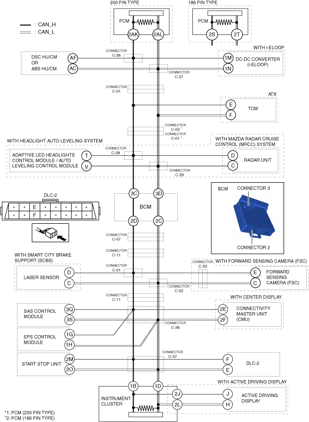
DETERMINING SHORT BETWEEN CIRCUITS LOCATION (HS-CAN) [SKYACTIV-G 1.3, SKYACTIV-G 1.5 (R.H.D.)]
id100220000800
System Wiring Diagram
am2zzw00014577
|
Determination Procedure
|
Step |
Inspection |
Action |
|
|---|---|---|---|
|
1
|
INSPECT BETWEEN BCM AND INSTRUMENT CLUSTER FOR SHORT BETWEEN CIRCUITS
• Switch the ignition off.
• Disconnect the negative battery cable.
• Disconnect the connector 2 and 3 which has BCM terminals 3C,3D and 2D,2C.
• Connect the negative battery cable.
• Switch the ignition ON (engine off).
• Measure the voltage at DLC-2 terminals F and E.
• Is the voltage at DLC-2 terminals F and E the same?
|
Yes
|
Go to Step 17.
|
|
No
|
Go to the next step.
|
||
|
2
|
INSPECT BCM FOR SHORT BETWEEN CIRCUITS
• Switch the ignition off.
• Disconnect the negative battery cable.
• Inspect for continuity between BCM terminals 3C and 3D.
• Is there continuity?
|
Yes
|
Replace the BCM because there is a short between circuits in the BCM.
|
|
No
|
Go to the next step.
|
||
|
3
|
INSPECT BETWEEN CONNECTORS C-28 AND C-29 AND BCM FOR SHORT BETWEEN CIRCUITS
• Connect the connector 2 and 3 which has BCM terminals 3C,3D and 2D,2C.
• Disconnect the connectors C-28 and C-29.
• Connect the negative battery cable.
• Switch the ignition ON (engine off).
• Measure the voltage at DLC-2 terminals F and E.
• Is the voltage at DLC-2 terminals F and E the same?
|
Yes
|
Repair or replace the wiring harness between the connectors C-28 and C-29 and BCM because the wiring harness is shorted between circuits.
|
|
No
|
Go to the next step.
|
||
|
4
|
INSPECT BETWEEN ADAPTIVE LED HEADLIGHTS CONTROL MODULE / AUTO LEVELING CONTROL MODULE AND CONNECTORS C-28 AND C-29 FOR SHORT BETWEEN CIRCUITS
• Switch the ignition off.
• Disconnect the negative battery cable.
• Inspect for continuity between adaptive LED headlights control module / auto leveling control module terminals T and V.
• Is there continuity?
|
Yes
|
Go to the next step.
|
|
No
|
Go to Step 6.
|
||
|
5
|
INSPECT ADAPTIVE LED HEADLIGHTS CONTROL MODULE / AUTO LEVELING CONTROL MODULE FOR SHORT BETWEEN CIRCUITS
• Disconnect the adaptive LED headlights control module / auto leveling control module connector.
• Inspect for continuity between adaptive LED headlights control module / auto leveling control module terminals T and V (wiring harness side).
• Is there continuity?
|
Yes
|
Repair or replace the wiring harness between the adaptive LED headlights control module / auto leveling control module and connectors C-28 and C-29 because the wiring harness is shorted between circuits.
|
|
No
|
Replace the adaptive LED headlights control module / auto leveling control module because there is a short between circuits in the adaptive LED headlights control module / auto leveling control module.
|
||
|
6
|
INSPECT BETWEEN RADAR UNIT AND CONNECTORS C-28 AND C-29 FOR SHORT BETWEEN CIRCUITS
• Inspect for continuity between radar unit terminals D and C.
• Is there continuity?
|
Yes
|
Go to the next step.
|
|
No
|
Go to Step 8.
|
||
|
7
|
INSPECT RADAR UNIT FOR SHORT BETWEEN CIRCUITS
• Disconnect the radar unit connector.
• Inspect for continuity between radar unit terminals D and C (wiring harness side).
• Is there continuity?
|
Yes
|
Repair or replace the wiring harness between the radar unit and connectors C-28 and C-29 because the wiring harness is shorted between circuits.
|
|
No
|
Replace the radar unit because there is a short between circuits in the radar unit.
|
||
|
8
|
INSPECT BETWEEN CONNECTOR C-01/C-02 AND CONNECTORS C-28 AND C-29 FOR SHORT BETWEEN CIRCUITS
• Disconnect the connector C-02. (PCM (200 pin type))
• Disconnect the connector C-01.
• Connect the connectors C-28,C-29.
• Connect the negative battery cable.
• Switch the ignition ON (engine off).
• Measure the voltage at DLC-2 terminals F and E.
• Is the voltage at DLC-2 terminals F and E the same?
|
Yes
|
Repair or replace the wiring harness between the connector C-01/C-02 and connectors C-28,C-29 because the wiring harness is shorted between circuits.
|
|
No
|
Go to the next step.
|
||
|
9
|
INSPECT BETWEEN TCM AND CONNECTOR C-01/C-02 FOR SHORT BETWEEN CIRCUITS
• Switch the ignition off.
• Disconnect the negative battery cable.
• Inspect for continuity between TCM terminals E and F.
• Is there continuity?
|
Yes
|
Go to the next step.
|
|
No
|
Go to Step 11.
|
||
|
10
|
INSPECT BETWEEN TCM AND CONNECTORS C-01, C-02 FOR SHORT BETWEEN CIRCUITS
• Disconnect TCM connector.
• Connect the connector C-02. (PCM (200 pin type))
• Connect the connector C-01. (PCM (186 pin type))
• Connect the negative battery cable.
• Switch the ignition ON (engine off).
• Measure the voltage at DLC-2 terminals F and E.
• Is the voltage at DLC-2 terminals F and E the same?
|
Yes
|
Repair or replace the wiring harness between the TCM and connector C-01/C-02 because the wiring harness is shorted between circuits.
|
|
No
|
Replace the TCM because there is a short between circuits in the TCM.
|
||
|
11
|
INSPECT BETWEEN CONNECTORS C-26, C-27 AND CONNECTOR C-01 FOR SHORT BETWEEN CIRCUITS
• Switch the ignition off.
• Disconnect the negative battery cable.
• Disconnect the connectors C-26, C-27.
• Connect the connector C-01.
• Connect the connector C-02. (PCM (200 pin type))
• Connect the negative battery cable.
• Switch the ignition ON (engine off).
• Measure the voltage at DLC-2 terminals F and E.
• Is the voltage at DLC-2 terminals F and E the same?
|
Yes
|
Repair or replace the wiring harness between the connectors C-26 and C-27 and connector C-01 because the wiring harness is shorted between circuits.
|
|
No
|
Go to the next step.
|
||
|
12
|
INSPECT BETWEEN DSC HU/CM OR ABS HU/CM AND CONNECTORS C-26, C-27 FOR SHORT BETWEEN CIRCUITS
• Switch the ignition off.
• Disconnect the negative battery cable.
• Inspect for continuity between DSC HU/CM terminals AF and AC.
• Is there continuity?
|
Yes
|
Go to the next step.
|
|
No
|
Go to Step 14.
|
||
|
13
|
INSPECT DSC HU/CM OR ABS HU/CM FOR SHORT BETWEEN CIRCUITS
• Disconnect the DSC HU/CM or ABS HU/CM connector.
• Inspect for continuity between DSC HU/CM or ABS HU/CM terminals AF and AC (wiring harness side).
• Is there continuity?
|
Yes
|
Repair or replace the wiring harness between the DSC HU/CM or ABS HU/CM and connectors C-26 and C-27 because the wiring harness is shorted between circuits.
|
|
No
|
Replace the DSC HU/CM or ABS HU/CM because there is a short between circuits in the DSC HU/CM or ABS HU/CM.
|
||
|
14
|
INSPECT BETWEEN DC-DC CONVERTER (i-ELOOP) AND CONNECTORS C-28 AND C-29 FOR SHORT BETWEEN CIRCUITS
• Inspect for continuity between DC-DC converter (i-ELOOP) terminals 1M and 1N.
• Is there continuity?
|
Yes
|
Go to the next step.
|
|
No
|
Go to Step 16.
|
||
|
15
|
INSPECT DC-DC CONVERTER (i-ELOOP) FOR SHORT BETWEEN CIRCUITS
• Disconnect the DC-DC converter (i-ELOOP) connector.
• Inspect for continuity between DC-DC converter (i-ELOOP) terminals 1M and 1N (wiring harness side).
• Is there continuity?
|
Yes
|
Repair or replace the wiring harness between the DC-DC converter (i-ELOOP) and connectors C-26 and C-27 because the wiring harness is shorted between circuits.
|
|
No
|
Replace the DC-DC converter (i-ELOOP) because there is a short between circuits in the DC-DC converter (i-ELOOP).
|
||
|
16
|
INSPECT PCM FOR SHORT BETWEEN CIRCUITS
• Disconnect the PCM connector.
• Inspect for continuity between PCM terminals 2AK and 2AL (wiring harness side).(PCM (200 pin type))
• Inspect for continuity between PCM terminals 2S and 2T (wiring harness side).(PCM (186 pin type))
• Is there continuity?
|
Yes
|
Repair or replace the wiring harness between the PCM and connectors C-26 and C-27 because the wiring harness is shorted between circuits.
|
|
No
|
Replace the PCM because there is a short between circuits in the PCM.
|
||
|
17
|
INSPECT BETWEEN CONNECTOR C-07 AND INSTRUMENT CLUSTER FOR SHORT BETWEEN CIRCUITS
• Switch the ignition off.
• Disconnect the negative battery cable.
• Disconnect the connector C-07.
• Connect the negative battery cable.
• Switch the ignition ON (engine off).
• Measure the voltage at DLC-2 terminals F and E.
• Is the voltage at DLC-2 terminals F and E the same?
|
Yes
|
Go to the next step.
|
|
No
|
Repair or replace the wiring harness between the BCM and connector C-07 because the wiring harness is shorted between circuits.
|
||
|
18
|
INSPECT BETWEEN CONNECTOR C-07 AND CONNECTOR C-11 FOR SHORT BETWEEN CIRCUITS
• Switch the ignition off.
• Disconnect the negative battery cable.
• Connect the connector C-07.
• Disconnect the connector C-11.
• Connect the negative battery cable.
• Switch the ignition ON (engine off).
• Measure the voltage at BCM terminals 2D and 2C.
• Is the voltage BCM terminals 2D and 2C the same?
|
Yes
|
Repair or replace the wiring harness between the connector C-07 and connector C-11 because the wiring harness is shorted between circuits.
|
|
No
|
Go to the next step.
|
||
|
19
|
INSPECT BETWEEN CONNECTOR C-11 AND INSTRUMENT CLUSTER FOR SHORT BETWEEN CIRCUITS
• Measure the voltage at DLC-2 terminals F and E.
• Is the voltage at DLC-2 terminals F and E the same?
|
Yes
|
Go to Step 26.
|
|
No
|
Go to the next step.
|
||
|
20
|
INSPECT BETWEEN CONNECTORS C-51,C-52 AND CONNECTOR C-11 FOR SHORT BETWEEN CIRCUITS
• Switch the ignition off.
• Disconnect the negative battery cable.
• Disconnect the connectors C-51,C-52.
• Connect the connector C-11.
• Connect the negative battery cable.
• Switch the ignition ON (engine off).
• Measure the voltage at DLC-2 terminals F and E.
• Is the voltage at DLC-2 terminals F and E the same?
|
Yes
|
Repair or replace the wiring harness between the connectors C-51,C-52 and connector C-11 because the wiring harness is shorted between circuits.
|
|
No
|
Go to the next step.
|
||
|
21
|
INSPECT BETWEEN LASER SENSOR AND CONNECTORS C-51,C-52 FOR SHORT BETWEEN CIRCUITS
• Switch the ignition off.
• Disconnect the negative battery cable.
• Inspect for continuity between laser sensor terminals D and C.
• Is there continuity?
|
Yes
|
Go to the next step.
|
|
No
|
Go to Step 23.
|
||
|
22
|
INSPECT LASER SENSOR FOR SHORT BETWEEN CIRCUITS
• Disconnect the laser sensor connector.
• Inspect for continuity between laser sensor terminals D and C (wiring harness side).
• Is there continuity?
|
Yes
|
Repair or replace the wiring harness between the laser sensor and connectors C-51,C-52 because the wiring harness is shorted between circuits.
|
|
No
|
Replace the laser sensor because there is a short between circuits in the laser sensor.
|
||
|
23
|
INSPECT BETWEEN FORWARD SENSING CAMERA (FSC) AND CONNECTORS C-51,C-52 FOR SHORT BETWEEN CIRCUITS
• Inspect for continuity between forward sensing camera (FSC) terminals E and C.
• Is there continuity?
|
Yes
|
Go to the next step.
|
|
No
|
Repair or replace the wiring harness between the connector C-11 and connectors C-51 and C-52 because the wiring harness is shorted between circuits.
|
||
|
24
|
INSPECT BETWEEN FORWARD SENSING CAMERA (FSC) AND CONNECTOR C-23 FOR SHORT BETWEEN CIRCUITS
• Disconnect the connector C-23.
• Inspect for continuity between forward sensing camera (FSC) terminals E and C.
• Is there continuity?
|
Yes
|
Go to the next step.
|
|
No
|
Repair or replace the wiring harness between the connectors C-51 and C-52 and connector C-23 because the wiring harness is shorted between circuits.
|
||
|
25
|
INSPECT FORWARD SENSING CAMERA (FSC) FOR SHORT BETWEEN CIRCUITS
• Disconnect the forward sensing camera (FSC) connector.
• Inspect for continuity between forward sensing camera (FSC) terminals E and C (wiring harness side).
• Is there continuity?
|
Yes
|
Repair or replace the wiring harness between the forward sensing camera (FSC) and connector C-23 because the wiring harness is shorted between circuits.
|
|
No
|
Replace the forward sensing camera (FSC) because there is a short between circuits in the forward sensing camera (FSC).
|
||
|
26
|
INSPECT BETWEEN CONNECTOR C-36 AND INSTRUMENT CLUSTER FOR SHORT BETWEEN CIRCUITS
• Switch the ignition off.
• Disconnect the negative battery cable.
• Disconnect the connector C-36.
• Connect the negative battery cable.
• Switch the ignition ON (engine off).
• Measure the voltage at DLC-2 terminals F and E.
• Is the voltage at DLC-2 terminals F and E the same?
|
Yes
|
Go to Step 33.
|
|
No
|
Go to the next step.
|
||
|
27
|
INSPECT BETWEEN CONNECTIVITY MASTER UNIT (CMU) AND CONNECTOS C-36 FOR SHORT BETWEEN CIRCUITS
• Switch the ignition off.
• Disconnect the negative battery cable.
• Inspect for continuity between connectivity master unit (CMU) terminals 2E and 2F.
• Is there continuity?
|
Yes
|
Go to the next step.
|
|
No
|
Go to Step 29.
|
||
|
28
|
INSPECT CONNECTIVITY MASTER UNIT (CMU) FOR SHORT BETWEEN CIRCUITS
• Disconnect the connectivity master unit (CMU) connector.
• Inspect for continuity between connectivity master unit (CMU) terminals 2E and 2F (wiring harness side).
• Is there continuity?
|
Yes
|
Repair or replace the wiring harness between the connectivity master unit (CMU) and connector C-36 because the wiring harness is shorted between circuits.
|
|
No
|
Replace the connectivity master unit (CMU) because there is a short between circuits in the connectivity master unit (CMU).
|
||
|
29
|
INSPECT BETWEEN EPS CONTROL MODULE AND CONNECTOR C-36 FOR SHORT BETWEEN CIRCUITS
• Inspect for continuity between EPS control module terminals 1G and 1H.
• Is there continuity?
|
Yes
|
Go to the next step.
|
|
No
|
Go to Step 31.
|
||
|
30
|
INSPECT EPS CONTROL MODULE FOR SHORT BETWEEN CIRCUITS
• Disconnect the EPS control module connector.
• Inspect for continuity between EPS control module terminals 1G and 1H (wiring harness side).
• Is there continuity?
|
Yes
|
Repair or replace the wiring harness between the EPS control module and connector C-36 because the wiring harness is shorted between circuits.
|
|
No
|
Replace the EPS control module because there is a short between circuits in the EPS control module.
|
||
|
31
|
INSPECT BETWEEN CONNECTOR C-11 AND CONNECTOR C-36 FOR SHORT BETWEEN CIRCUITS
• Switch the ignition off.
• Disconnect the negative battery cable.
• Connect the connector C-11.
• Connect the negative battery cable.
• Switch the ignition ON (engine off).
• Measure the voltage at BCM terminals 2D and 2C (wiring harness side).
• Is the voltage BCM terminals 2D and 2C (wiring harness side) the same?
|
Yes
|
Repair or replace the wiring harness between the connector C-11 and connector C-36 because the wiring harness is shorted between circuits.
|
|
No
|
Go to the next step.
|
||
|
32
|
INSPECT SAS CONTORL MODULE FOR SHORT BETWEEN CIRCUITS
• Switch the ignition off.
• Disconnect the negative battery cable.
• Disconnect the SAS control module connector.
• Inspect for continuity between SAS control module terminals 3Q and 3S (wiring harness side).
• Is there continuity?
|
Yes
|
Repair or replace the wiring harness between the SAS control module and connector C-36 because the wiring harness is shorted between circuits.
|
|
No
|
Replace the SAS control module because there is a short between circuits in the SAS control module.
|
||
|
33
|
INSPECT BETWEEN CONNECTOR C-37 AND DLC-2 FOR SHORT BETWEEN CIRCUITS
• Switch the ignition off.
• Disconnect the negative battery cable.
• Disconnect the connector C-37.
• Inspect for continuity between DLC-2 terminals F and E.
• Is there continuity?
|
Yes
|
Repair or replace the wiring harness between connector C-37 and DLC-2 because the wiring harness is shorted between circuits.
|
|
No
|
Go to the next step.
|
||
|
34
|
INSPECT BETWEEN START STOP UNIT AND CONNECTOR C-37 FOR SHORT BETWEEN CIRCUITS
• Is there continuity between start stop unit terminals 2M and 2O.
• Is there continuity?
|
Yes
|
Go to the next step.
|
|
No
|
Go to Step 36.
|
||
|
35
|
INSPECT START STOP UNIT FOR SHORT BETWEEN CIRCUITS
• Disconnect the start stop unit connector.
• Is there continuity between start stop unit terminals 2M and 2O (wiring harness side).
• Is there continuity?
|
Yes
|
Repair or replace the wiring harness between the start stop unit and connector C-37 because the wiring harness is shorted between circuits.
|
|
No
|
Replace the start stop unit because there is a short between circuits in the start stop unit.
|
||
|
36
|
INSPECT BETWEEN CONNECTOR C-36 AND CONNECTOR C-37 FOR SHORT BETWEEN CIRCUITS
• Connect the negative battery cable.
• Switch the ignition ON (engine off).
• Measure the voltage at instrument cluster terminals 1B and 1D.
• Is the voltage instrument cluster terminals 1B and 1D the same?
|
Yes
|
Go to the next step.
|
|
No
|
Repair or replace the wiring harness between connector C-36 and connector C-37 because the wiring harness is shorted between circuits.
|
||
|
37
|
INSPECT BETWEEN INSTRUMENT CLUSTER AND CONNECTOR C-37 FOR SHORT BETWEEN CIRCUITS
• Switch the ignition off.
• Disconnect the negative battery cable.
• Disconnect the instrument cluster connector.
• Connect the connector C-37.
• Connect the negative battery cable.
• Switch the ignition ON (engine off).
• Measure the voltage at DLC-2 terminals F and E.
• Is the voltage at DLC-2 terminals F and E the same?
|
Yes
|
Repair or replace the wiring harness between the instrument cluster and connector C-37 because the wiring harness is shorted between circuits.
|
|
No
|
Go to the next step.
|
||
|
38
|
INSPECT BETWEEN INSTRUMENT CLUSTER AND ACTIVE DRIVING DISPLAY FOR SHORT BETWEEN CIRCUITS
• Switch the ignition off.
• Disconnect the negative battery cable.
• Inspect for continuity between active driving display terminals J and H.
• Is there continuity?
|
Yes
|
Go to the next step.
|
|
No
|
Replace the instrument cluster because there is a short between circuits in the instrument cluster.
|
||
|
39
|
INSPECT ACTIVE DRIVING DISPLAY FOR SHORT BETWEEN CIRCUITS
• Disconnect the active driving display connector.
• Inspect for continuity between active driving display terminals J and H (wiring harness side).
• Is there continuity?
|
Yes
|
Repair or replace the wiring harness between the instrument cluster and active driving display because the wiring harness is shorted between circuits.
|
|
No
|
Replace the active driving display because there is a short between circuits in the active driving display.
|
||