 |
am2zzw00000124
VARIABLE VALVE TIMING ACTUATOR INSPECTION [ZJ, ZY]
id0110b7801200
1. Disconnect the negative battery cable.
2. Perform the following procedure.
3. Remove the ignition coils. (See IGNITION COIL REMOVAL/INSTALLATION [ZJ, ZY].)
4. Disconnect the ventilation hose. (See INTAKE-AIR SYSTEM REMOVAL/INSTALLATION [ZJ, ZY].)
5. Set the vacuum hose out of the way. (See INTAKE-AIR SYSTEM REMOVAL/INSTALLATION [ZJ, ZY].)
6. Remove the cylinder head cover. (See TIMING CHAIN REMOVAL/INSTALLATION [ZJ, ZY].)
7. Remove the splash shield (RH). (See DRIVE BELT REMOVAL/INSTALLATION [ZJ, ZY].)
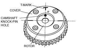
8. Verify that the camshaft knock pin hole of the variable valve timing actuator and the T- mark of the cover are aligned and fixed as shown in the figure.
am2zzw00000124
|
9. Install the splash shield (RH). (See DRIVE BELT REMOVAL/INSTALLATION [ZJ, ZY].)
10. Install the cylinder head cover. (See TIMING CHAIN REMOVAL/INSTALLATION [ZJ, ZY].)
11. Connect the ventilation hose. (See INTAKE-AIR SYSTEM REMOVAL/INSTALLATION [ZJ, ZY].)
12. Install the ignition coils. (See IGNITION COIL REMOVAL/INSTALLATION [ZJ, ZY].)
13. Install the fresh-air duct and the air cleaner as a single unit. (See INTAKE-AIR SYSTEM REMOVAL/INSTALLATION [ZJ, ZY].)