VALVE CLEARANCE INSPECTION [ZJ, ZY]
id0110b7803400
1. Disconnect the negative battery cable.
2. Remove the splash shield (RH). (See DRIVE BELT REMOVAL/INSTALLATION [ZJ, ZY].)
3. Perform the following procedure.
-
Except U.K. specs.
-
-
U.K. specs.
-
4. Remove the ignition coils. (See IGNITION COIL REMOVAL/INSTALLATION [ZJ, ZY].)
5. Disconnect the ventilation hose. (SeeINTAKE-AIR SYSTEM REMOVAL/INSTALLATION [ZJ, ZY].)
6. Set the vacuum hose out of the way. (See INTAKE-AIR SYSTEM REMOVAL/INSTALLATION [ZJ, ZY].)
7. Remove the cylinder head cover. (See TIMING CHAIN REMOVAL/INSTALLATION [ZJ, ZY].)
8. Measure the valve clearance.
-
Note
-
• Make sure to note down the measured values for choosing the suitable replacement tappets.
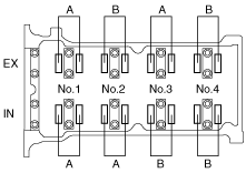
- (1) Rotate the crankshaft clockwise so that the No.1 cylinder is at TDC of the compression stroke.
- (2) Measure the valve clearance at A in the figure.
-
-
-
Valve clearance [Engine cold]
-
IN: 0.27—0.33 mm {0.0107—0.0129 in}
EX: 0.27—0.33 mm {0.0107—0.0129 in}
- (3) Rotate the crankshaft clockwise 360° so that the No.4 cylinder is at TDC of the compression stroke.
- (4) Measure the valve clearance at B in the figure.
-
-
-
Valve clearance [Engine cold]
-
IN: 0.27—0.33 mm {0.0107—0.0129 in}
EX: 0.27—0.33 mm {0.0107—0.0129 in}
9. Install the cylinder head cover. (See TIMING CHAIN REMOVAL/INSTALLATION [ZJ, ZY].)
10. Connect the ventilation hose. (See INTAKE-AIR SYSTEM REMOVAL/INSTALLATION [ZJ, ZY].)
11. Install the ignition coils. (See IGNITION COIL REMOVAL/INSTALLATION [ZJ, ZY].)
12. Install the fresh-air duct and the air cleaner as a single unit. (See INTAKE-AIR SYSTEM REMOVAL/INSTALLATION [ZJ, ZY].)
13. Install the splash shield (RH). (See DRIVE BELT REMOVAL/INSTALLATION [ZJ, ZY].)