 |
am2zzw00003062
CYLINDER HEAD GASKET REPLACEMENT [MZ-CD 1.4 DI Turbo]
id0110b8800700
1. Disconnect the negative battery cable. (See BATTERY REMOVAL/INSTALLATION [MZ-CD 1.4 DI Turbo].)
2. Drain the engine coolant. (See ENGINE COOLANT REPLACEMENT [MZ-CD 1.4 DI Turbo].)
3. Remove the following parts:
4. Remove the wiring harness and wiring harness bracket from the upper timing belt cover.
5. Set the cooler hose out of the way (With A/C). (See REFRIGERANT LINE REMOVAL/INSTALLATION.)
6. Remove the intake-air system. (See INTAKE-AIR SYSTEM REMOVAL/INSTALLATION [MZ-CD 1.4 DI Turbo].)
7. Remove the timing belt. (See TIMING BELT REMOVAL/INSTALLATION [MZ-CD 1.4 DI Turbo].)
8. Remove the hydraulic lash adjuster (HLA). (See HYDRAULIC LASH ADJUSTER (HLA) REMOVAL/INSTALLATION [MZ-CD 1.4 DI Turbo].)
9. Remove the fuel injector. (See FUEL INJECTOR REMOVAL/INSTALLATION [MZ-CD 1.4 DI Turbo].)
10. Remove the generator. (See GENERATOR REMOVAL/INSTALLATION [MZ-CD 1.4 DI Turbo].)
11. Remove the catalytic converter. (See EXHAUST SYSTEM REMOVAL/INSTALLATION [MZ-CD 1.4 DI Turbo].)
12. Set the oil pipe and oil hose out of the way. (See EXHAUST SYSTEM REMOVAL/INSTALLATION [MZ-CD 1.4 DI Turbo].)
13. Remove the battery. (See BATTERY REMOVAL/INSTALLATION [MZ-CD 1.4 DI Turbo].)
14. Remove the battery tray. (See PCM REMOVAL/INSTALLATION [MZ-CD 1.4 DI Turbo].)
15. Disconnect the coolant reserve tank hose, upper radiator hose, heater hose, ECT sensor electrical connector and bypass hose. (See THERMOSTAT REMOVAL/INSTALLATION [MZ-CD 1.4 DI Turbo].)
16. Remove the supply pump. (See SUPPLY PUMP REMOVAL/INSTALLATION [MZ-CD 1.4 DI Turbo].)
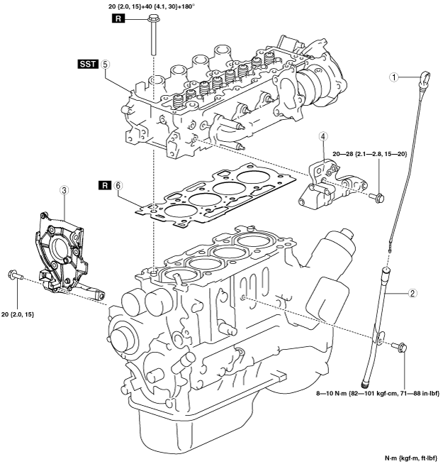
17. Remove in the order indicated in the table.
18. Install in the reverse order of removal.
am2zzw00003062
|
|
1
|
Oil level gauge
|
|
2
|
Oil level gauge pipe
|
|
3
|
Supply pump bracket
|
|
4
|
Generator bracket
|
|
5
|
Cylinder head
(See Cylinder Head Removal Note.)
|
|
6
|
Cylinder head gasket
|
Cylinder Head Removal Note
1. Loosen the cylinder head bolts in 2—3 passes in the order shown in the figure.
am2zzw00003040
|
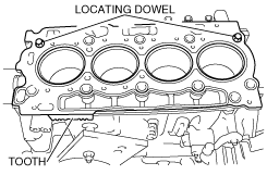
Cylinder Head Gasket Installation Note
|
Number of teeth |
Piston protrusion |
Gasket thickness |
|---|---|---|
|
1
|
0.7760—0.8250 mm {0.03056—0.03248 in}
|
1.35 mm {0.0531 in}
|
|
2
|
0.6175—0.7250 mm {0.02432—0.02854 in}
|
1.25 mm {0.0492 in}
|
|
3
|
0.7260—0.7750 mm {0.02859—0.03051 in}
|
1.30 mm {0.0512 in}
|
|
4
|
0.8260—0.8750 mm {0.03252—0.03444 in}
|
1.40 mm {0.0551 in}
|
|
5
|
0.8760—0.9830 mm {0.03449—0.03870 in}
|
1.45 mm {0.0571 in}
|
1. Install a new cylinder head gasket.
am2zzw00003057
|
Cylinder Head Installation Note
1. Tighten the new cylinder head installation bolts using the SST (49 D032 316) in three steps in the order shown in the figure.
am2zzw00003059
|