1. Remove the clutch master cylinder
(SeeCLUTCH MASTER CYLINDER REMOVAL/INSTALLATION.)
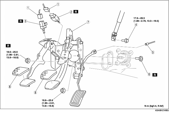
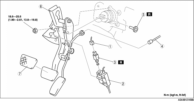
2. Remove in the order indicated in the table.
3. Install in the reverse order of removal.
4. After installation, adjust the accelerator pedal.(SeeACCELERATOR CABLE INSPECTION/ADJUSTMENT.)
5. Bleed the air from the clutch.(SeeCLUTCH FLUID REPLACEMENT.)
|
1
|
Connector
|
|
2
|
Brake switch
|
|
3
|
Clutch switch
|
|
4
|
Intermediate shaft lower side bolt
|
|
5
|
Accelerator cable
|
|
6
|
Joint pin
(See Joint pin removal note)
|
|
7
|
Pedal component
|
|
8
|
Pedal pad
|
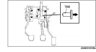
1. Loosen the pedal component installation nut.
2. Remove the joint pin while pressing the tab of the joint pin.
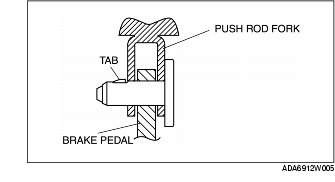
1. Install the new joint pin by aligning the pin holes of brake pedal and push rod fork, before installing the pedal component completely.
2. Make sure that the joint pin tab is caught correctly.
3. Tighten the pedal component installation nuts.
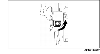
1. Install the new brake switch to the pedal component, and secure the brake switch by turning it as shown in the figure.
2. With the brake pedal in its original position, install the brake switch to the brake switch connector.
1. Remove in the order indicated in the table.
2. Install in the reverse order of removal.
3. After installation, adjust the accelerator pedal. (See ACCELERATOR CABLE INSPECTION/ADJUSTMENT.)
4. After installation, inspect the shift-lock and key interlock. (See SHIFT-LOCK INSPECTION.) (See KEY INTERLOCK INSPECTION.)
|
1
|
Brake switch connector
|
|
2
|
Interlock unit
|
|
3
|
Brake switch
|
|
4
|
Accelerator cable
|
|
5
|
Joint pin
(See Joint pin removal note)
|
|
6
|
Pedal component
|
|
7
|
Pedal pad
|
1. Install the new brake switch to the interlock unit, and secure the brake switch by turning it as shown in the figure.
2. With the brake pedal in its original position, install the brake switch to the brake switch connector.