 |
acmzzw00000118
DTC P0335:00 [MZ-CD 1.6]
id0102g8703600
Specification identification
acmzzw00000118
|
|
DTC P0335:00 |
Crankshaft position (CKP) sensor circuit malfunction |
|---|---|
|
DETECTION CONDITION
|
• The PCM monitors the CKP sensor signal. If there is no CKP sensor signal, the PCM determines that the CKP sensor circuit has a malfunction.
|
|
POSSIBLE CAUSE
|
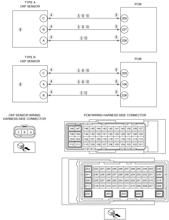
Type A
• CKP sensor connector or terminal malfunction
• Short to power supply in wiring harness between CKP sensor terminal A and PCM terminal 228
• Short to power supply in wiring harness between CKP sensor terminal B and PCM terminal 227
• Short to power supply in wiring harness between CKP sensor terminal C and PCM terminal 209
• Short to ground circuit in wiring harness between CKP sensor terminal B and PCM terminal 227
• Short to ground circuit in wiring harness between CKP sensor terminal C and PCM terminal 209
• CKP sensor pulse wheel malfunction
• CKP sensor malfunction
• PCM connector or terminal malfunction
• Open circuit in wiring harness between CKP sensor terminal A and PCM terminal 228
• Open circuit in wiring harness between CKP sensor terminal B and PCM terminal 227
• Open circuit in wiring harness between CKP sensor terminal C and PCM terminal 209
• PCM malfunction
Type B
• CKP sensor connector or terminal malfunction
• Short to power supply in wiring harness between CKP sensor terminal B and PCM terminal 228
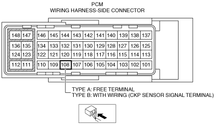
• Short to power supply in wiring harness between CKP sensor terminal A and PCM terminal 108
• Short to power supply in wiring harness between CKP sensor terminal C and PCM terminal 209
• Short to ground circuit in wiring harness between CKP sensor terminal A and PCM terminal 108
• Short to ground circuit in wiring harness between CKP sensor terminal C and PCM terminal 209
• CKP sensor pulse wheel malfunction
• CKP sensor malfunction
• PCM connector or terminal malfunction
• Open circuit in wiring harness between CKP sensor terminal B and PCM terminal 228
• Open circuit in wiring harness between CKP sensor terminal A and PCM terminal 108
• Open circuit in wiring harness between CKP sensor terminal C and PCM terminal 209
• PCM malfunction
|
 |
|
Diagnostic procedure
|
STEP |
INSPECTION |
ACTION |
|
|---|---|---|---|
|
1
|
VERIFY FREEZE FRAME DATA HAS BEEN RECORDED
• Has the FREEZE FRAME DATA been recorded?
|
Yes
|
Go to the next step.
|
|
No
|
Record the FREEZE FRAME DATA on the repair order, then go to the next step.
|
||
|
2
|
VERIFY RELATED REPAIR INFORMATION AVAILABILITY
• Verify related service repair information availability.
• Is any related repair information available?
|
Yes
|
Perform repair or diagnosis according to the available repair information.
• If the vehicle is not repaired, go to the next step.
|
|
No
|
Go to the next step.
|
||
|
3
|
VERIFY RELATED PENDING CODE AND/OR DTC
• Switch the ignition to ON (engine off).
• Perform the Pending Trouble Code Access Procedure and DTC Reading Procedure.
• Is the other PENDING CODE/DTC also present?
|
Yes
|
Go to the applicable DTC inspection.
(See DTC TABLE [MZ-CD 1.6].)
|
|
No
|
Go to the next step.
|
||
|
4
|
INSPECT CKP SENSOR CONNECTOR CONDITION
• Switch the ignition to off.
• Disconnect the CKP sensor connector.
• Inspect for poor connection (such as damaged/pulled-out pins, corrosion)
• Is there any malfunction?
|
Yes
|
Repair or replace the connector and/or terminals, then go to Step 11.
|
|
No
|
Go to the next step.
|
||
|
5
|
INSPECT CKP SENSOR CIRCUIT FOR SHORT TO POWER SUPPLY
• Disconnect the CKP sensor and PCM connectors.
• Switch the ignition to ON (engine off).
• Measure the voltage between the following terminals (wiring harness-side):
• Is the voltage B+?
|
Yes
|
Repair or replace the wiring harness for a possible short to power supply, then go to Step 11.
|
|
No
|
Go to the next step.
|
||
|
6
|
INSPECT CKP SENSOR CIRCUIT FOR SHORT TO GROUND
• Switch the ignition to off.
• Disconnect the CKP sensor connector.
• Inspect for continuity between CKP sensor and body ground at following wiring harness-side connector:
Type A
Type B
• Is there continuity?
|
Yes
|
If the short to ground circuit could be detected:
• Repair or replace the wiring harness for a possible short to ground.
If the short to ground circuit could not be detected:
• Replace the PCM (short to ground in the PCM internal circuit).
Go to Step 11.
|
|
No
|
Go to the next step.
|
||
|
7
|
INSPECT CKP SENSOR PULSE WHEEL
• Visually inspect the CKP sensor pulse wheel (crankshaft pulley).
• Is there any malfunction?
|
Yes
|
Replace the crankshaft pulley, then go to Step 11.
|
|
No
|
Go to the next step.
|
||
|
8
|
INSPECT CKP SENSOR
• Inspect the CKP sensor.
• Is there any malfunction?
|
Yes
|
Replace the CKP sensor, then go to Step 11.
|
|
No
|
Go to the next step.
|
||
|
9
|
INSPECT PCM CONNECTOR CONDITION
• Disconnect the PCM connector.
• Inspect for poor connection (such as damaged/pulled-out pins, corrosion)
• Is there any malfunction?
|
Yes
|
Repair or replace the connector and/or terminals, then go to Step 11.
|
|
No
|
Go to the next step.
|
||
|
10
|
INSPECT CKP SENSOR CIRCUIT FOR OPEN
• Inspect for continuity between CKP sensor and PCM at following wiring harness-side connector:
Type A
Type B
• Is there continuity?
|
Yes
|
Go to the next step.
|
|
No
|
Repair or replace the wiring harness for a possible open circuit, go to the next step.
|
||
|
11
|
VERIFY THAT DTC P0335:00 TROUBLESHOOTING IS COMPLETED
• Make sure to reconnect all disconnected connectors.
• Clear the DTC from the PCM memory using the M-MDS.
• Run the vehicle under the FREEZE FRAME DATA stored condition.
• Is the same DTC present?
|
Yes
|
Repeat the inspection from Step 1.
• If the malfunction recurs, replace the PCM.
Go to the next step.
|
|
No
|
Go to the next step.
|
||
|
12
|
VERIFY AFTER REPAIR PROCEDURE
• Perform the after repair procedure.
• Are any DTCs present?
|
Yes
|
Go to the applicable DTC inspection.
(See DTC TABLE [MZ-CD 1.6].)
|
|
No
|
DTC troubleshooting completed.
|
||