 |
am2zzw00006407
SUPPLY PUMP REMOVAL/INSTALLATION [MZ-CD 1.6]
id011420805700
L.H.D.
1. Disconnect the negative battery cable. (See BATTERY REMOVAL/INSTALLATION [MZ-CD 1.6].)
2. Remove the fuel metering valve. (See FUEL METERING VALVE REMOVAL/INSTALLATION [MZ-CD 1.6].)
3. Remove the following parts:
4. Set the cooler hose (LO) out of the way. (See REFRIGERANT LINE REMOVAL/INSTALLATION [MZ-CD 1.6].)
5. Remove the timing belt. (See TIMING BELT REMOVAL/INSTALLATION [MZ-CD 1.6].)
6. Remove and dispose of the injection pipe (supply pump side). (See COMMON RAIL REMOVAL/INSTALLATION [MZ-CD 1.6].)
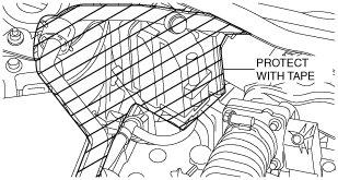
7. The position shown in figure is protected with the tape.
am2zzw00006407
|
8. Remove the nut using the SST as shown in the figure.
am2zzw00006408
|
9. Remove the bolt as shown in the figure.
am2zzw00006409
|
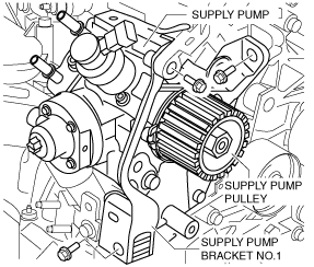
10. Remove the supply pump and supply pump bracket No.1 and supply pump pulley as single unit.
am2zzw00006410
|
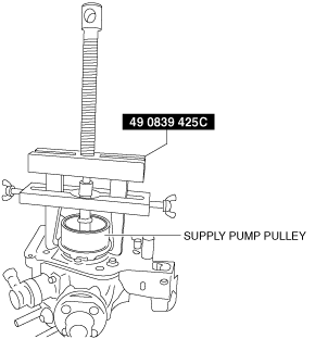
11. Install the SST as shown in the figure.
am2zzw00006411
|
12. Remove the supply pump pulley.
13. Remove the supply pump.
am2zzw00006412
|
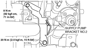
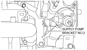
14. Remove the supply pump bracket No.2.
15. Install in the reverse order of removal. (See Supply Pump Bracket No.2 Installation Note.)
R.H.D.
1. Disconnect the negative battery cable. (See BATTERY REMOVAL/INSTALLATION [MZ-CD 1.6].)
2. Remove the fuel metering valve. (See FUEL METERING VALVE REMOVAL/INSTALLATION [MZ-CD 1.6].)
3. Remove the following parts:
4. Set the cooler hose (LO) out of the way. (See REFRIGERANT LINE REMOVAL/INSTALLATION [MZ-CD 1.6].)
5. Remove the timing belt. (See TIMING BELT REMOVAL/INSTALLATION [MZ-CD 1.6].)
6. Remove and dispose of the injection pipe (supply pump side). (See COMMON RAIL REMOVAL/INSTALLATION [MZ-CD 1.6].)
7. Remove the nut using the SST as shown in the figure.
am2zzw00006408
|
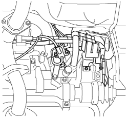
8. Set the components shown in the figure out of the way.
am2zzw00006413
|
9. Remove the middle pipe installation nut (front pipe side). (See EXHAUST SYSTEM REMOVAL/INSTALLATION [MZ-CD 1.6].)
10. Remove the No.1 engine mount installation bolt. (See ENGINE REMOVAL/INSTALLATION [MZ-CD 1.6].)
11. Remove the bolt as shown in the figure.
am2zzw00006409
|
12. Push the engine in the direction towards the front of the vehicle and remove the supply pump, supply pump bracket No.1, and supply pump pulley as a single unit from the space shown in the figure.
am2zzw00006414
|
13. Install the SST as shown in the figure.
am2zzw00006411
|
14. Remove the supply pump pulley.
15. Remove the supply pump.
am2zzw00006412
|
16. Remove supply pump bracket No.2.
17. Install in the reverse order of removal. (See Supply Pump Bracket No.2 Installation Note.)
Supply Pump Bracket No.2 Installation Note
1. Temporarily tighten supply pump bracket No.2 using the bolt shown in the figure.
am2zzw00006415
|
2. Install the supply pump and supply pump bracket No.1 and supply pump pulley as single unit.
3. Install supply pump bracket No.2.