STEP
INSPECTION
ACTION
1
• Start the engine.
-
― Does the tachometer needle move smoothly?― Does the tachometer needle indicate correct engine speed?
Yes
Troubleshooting completed. (The system is normal.)
No
Go to the next step.
2
• Reactive the DTC of PCM using M-MDS.
• Is the DTC detected?
Yes
Go to applicable DTC troubleshooting procedure.
(See DTC TABLE [MZR 1.3, MZR 1.5].)
(See DTC TABLE [MZ-CD 1.6].)
No
Go to the next step.
3
• Start the engine.
• Verify that the tachometer indication and high engine coolant temperature warning light illumination.
• Do the tachometer and high engine coolant temperature warning light work properly?
Yes
Go to the next step.
No
Go to Step 5.
4
• Monitor the PCM PID RPM using the M-MDS.
• Start the engine and compare the M-MDS monitored value with the tachometer indication.
• Does the M-MDS monitored value correspond to the tachometer indication?
Yes
Verify that the PCM connector is connected securely.
If the PCM connector is poor connection:
Connect the PCM connector securely.
If malfunction is in the PCM side connector:
Replace the PCM.
If malfunction is in vehicle side connector:
Repair or replace malfunctioning part.
No
Replace the instrument cluster.
5
• Reactive the DTC of instrument cluster using M-MDS.
• Is the DTC detected?
Yes
Go to the applicable DTC troubleshooting procedure.
No
Go to the next step.
6
• Disconnect the negative battery cable.
• Measure the resistance between the DLC-2 terminals F and E.
• Is the resistance below 60 ohms?
Yes
Go to the next step.
No
Go to Step 8.
7
• Disconnect the negative battery cable.
• Inspect the DLC-2 terminals F and E for short to power supply or ground.
• Is there any malfunction?
Yes
Inspect the wiring harness and CAN system-related module.
Repair or replace the malfunctioning part.
No
Replace the instrument cluster.
8
• Turn the ignition switch off.
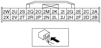
• Inspect the instrument cluster connector terminals for poor connection (such as damaged/pulled-out pins, and corrosion).
• Are the terminals normal?
Yes
Go to the next step.
No
Repair or replace the terminal.
9
• Disconnect the negative battery cable.
• Measure the resistance between the instrument cluster connector terminals 2B and 2D.
• Is the resistance 114—126 ohms?
Yes
Inspect the wiring harness and CAN system-related module.
Repair or replace the malfunctioning part.
No
Replace the instrument cluster.