 |
am3uuw00003442
OIL PUMP REMOVAL/INSTALLATION [LF, L5]
id0111c4800600
1. Remove the battery cover. (See BATTERY REMOVAL/INSTALLATION [LF, L5].)
2. Disconnect the negative battery cable.
3. Remove the plug hole plate. (See PLUG HOLE PLATE REMOVAL/INSTALLATION [LF, L5].)
4. Disconnect the wiring harness.
5. Remove the ignition coils. (See IGNITION COIL REMOVAL/INSTALLATION [LF, L5].)
6. Remove the spark plugs. (See SPARK PLUG REMOVAL/INSTALLATION [LF, L5].)
7. Remove the ventilation hose.
8. Remove the coolant reserve tank with the hose still connected and set it out of the way. (See COOLANT RESERVE TANK REMOVAL/INSTALLATION [LF, L5].)
9. Remove the front wheel and tire. (RH) (See GENERAL PROCEDURES (SUSPENSION).)
10. Remove the aerodynamic under cover No.2 and splash shield as a single unit. (See AERODYNAMIC UNDER COVER NO.2 REMOVAL/INSTALLATION.)(See SPLASH SHIELD REMOVAL/INSTALLATION.)
11. Drain the engine oil. (See ENGINE OIL REPLACEMENT [LF, L5].)
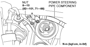
12. Remove the nut shown in the figure and set the power steering pipe component out of the way.
LF
am3uuw00003442
|
L5
am3uuw00002800
|
13. Remove the drive belt. (See DRIVE BELT REMOVAL/INSTALLATION [LF, L5].)
14. Remove the crankshaft position (CKP) sensor. (See CRANKSHAFT POSITION (CKP) SENSOR REMOVAL/INSTALLATION [LF, L5].)
15. Remove the A/C compressor with the cooler hose still connected and secure it using wire or rope so that it is out of the way. (LF) (See A/C COMPRESSOR REMOVAL/INSTALLATION.)
16. Disconnect the drive shaft (RH) from joint shaft, set the drive shaft (RH) out of the way. (MTX) (See DRIVE SHAFT REMOVAL/INSTALLATION.)
17. Remove the engine front cover. (See TIMING CHAIN REMOVAL/INSTALLATION [LF, L5].)
18. Remove the oil pan. (See OIL PAN REMOVAL/INSTALLATION [LF, L5].)
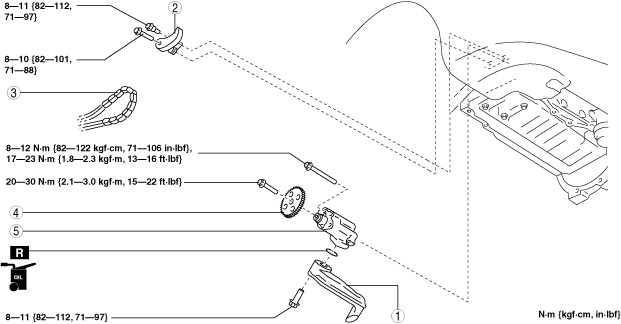
19. Remove in the order indicated in the table.
20. Install in the reverse order of removal.
21. Refill with the specified type and amount of the engine oil. (See ENGINE OIL REPLACEMENT [LF, L5].)
22. Start the engine and confirm that there is no oil leakage.
23. Inspect the oil level. (See ENGINE OIL LEVEL INSPECTION [LF, L5].)
24. Inspect for the ignition timing and idle speed. (See ENGINE TUNE-UP [LF, L5].)
25. Inspect the oil pressure. (See OIL PRESSURE INSPECTION [LF, L5].)
am3zzw00021095
|
|
1
|
Oil strainer
|
|
2
|
Oil pump chain tensioner
|
|
3
|
Oil pump chain
|
|
4
|
Oil pump sprocket
|
|
5
|
Oil pump
(See Oil Pump Installation Note.)
|
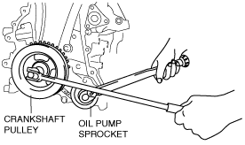
Oil Pump Sprocket Removal/Installation Note
1. Temporarily install the crankshaft pulley and crankshaft pulley lock bolt to the crankshaft, and lock the oil pump against rotation as shown in figure.
am3uuw00002265
|
2. Remove/install the oil pump sprocket, and then remove the crankshaft pulley and crankshaft pulley lock bolt.
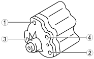
Oil Pump Installation Note
1. Tighten the oil pump bolts in two steps in the order shown in the figure.
am6zzw00002315
|