 |
am3uuw00002257
FUEL TANK REMOVAL/INSTALLATION [LF, L5]
id0114a7801600
1. Level the vehicle.
2. Complete the “BEFORE SERVICE PRECAUTION”. (See BEFORE SERVICE PRECAUTION [LF, L5].)
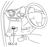
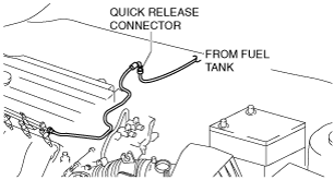
3. Disconnect the quick release connector. (See QUICK RELEASE CONNECTOR REMOVAL/INSTALLATION [LF, L5].)
am3uuw00002257
|
4. Connect a long hose to the disconnected quick release connector and drain the fuel into a container used for collecting gasoline.
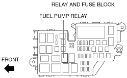
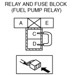
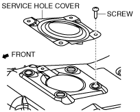
5. Drain the fuel from the fuel tank using the following procedure:
am3uuw00002786
|
am3uuw00002787
|
am6zzw00000268
|
6. Stop the fuel pump using the following procedure.
7. Remove the following parts:
am3zzw00006385
|
8. Remove the following parts:
9. Remove the under cover (LH). (See REAR TRAILING LINK REMOVAL/INSTALLATION.)
10. Remove the insulator (middle No.1). (See EXHAUST SYSTEM REMOVAL/INSTALLATION [LF, L5].)
11. Remove in the order indicated in the table.
12. Install in the reverse order of removal.
13. Complete the “AFTER SERVICE PRECAUTION”. (See AFTER SERVICE PRECAUTION [LF, L5].)
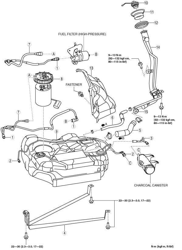
LF (Fuel filter (high-pressure) is a built-in type in fuel pump unit)
am3zzw00007804
|
|
1
|
Quick release connector
|
|
2
|
Quick release connector
|
|
3
|
Evaporative hose
|
|
4
|
Fuel tank strap
|
|
5
|
Joint hose
(See Joint Hose Removal Note.)
(See Joint Hose Installation Note.)
|
|
6
|
Breather hose
(See Breather Hose Removal Note.)
|
|
7
|
Fuel hose
|
|
8
|
Fuel pump unit
|
|
9
|
Fuel tank component
|
|
10
|
Fuel-filler cap
|
|
11
|
Protector
|
|
12
|
Dust cover
|
|
13
|
Fuel-filler pipe
|
|
14
|
Nonreturn valve
|
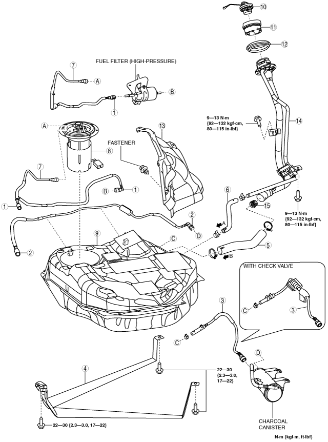
LF (Fuel filter (high-pressure) is not a built-in type in fuel pump unit)
am3zzw00007805
|
|
1
|
Quick release connector
|
|
2
|
Quick release connector
|
|
3
|
Evaporative hose
|
|
4
|
Fuel tank strap
|
|
5
|
Joint hose
(See Joint Hose Removal Note.)
(See Joint Hose Installation Note.)
|
|
6
|
Breather hose
(See Breather Hose Removal Note.)
|
|
7
|
Fuel hose
|
|
8
|
Fuel pump unit
|
|
9
|
Fuel tank component
|
|
10
|
Fuel-filler cap
|
|
11
|
Protector
|
|
12
|
Dust cover
|
|
13
|
Fuel-filler pipe protector
|
|
14
|
Fuel-filler pipe
|
|
15
|
Nonreturn valve
|
L5
am3zzw00011135
|
|
1
|
Quick release connector
|
|
2
|
Quick release connector
|
|
3
|
Evaporative hose
|
|
4
|
Fuel tank strap
|
|
5
|
Joint hose
(See Joint Hose Removal Note.)
(See Joint Hose Installation Note.)
|
|
6
|
Breather hose
(See Breather Hose Removal Note.)
|
|
7
|
Fuel hose
|
|
8
|
Fuel pump unit
|
|
9
|
Fuel tank component
|
|
10
|
Fuel-filler cap
|
|
11
|
Protector
|
|
12
|
Dust cover
|
|
13
|
Fuel-filler pipe protector
|
|
14
|
Fuel-filler pipe
|
|
15
|
Nonreturn valve
|
Joint Hose Removal Note
1. Remove the charcoal canister. (See CHARCOAL CANISTER REMOVAL/INSTALLATION [LF, L5].)
2. Remove the fuel-filler pipe installation bolts.
3. Remove the joint hose.
Breather Hose Removal Note
1. Disconnect the breather hose of fuel-filler pipe side.
2. Remove the following parts as a single unit.
3. Remove the breather hose.
Fuel-Filler Pipe Removal Note
1. Remove the rear tire (RH). (See GENERAL PROCEDURES (SUSPENSION).)
2. Remove the mudguard (RH) (Vehicles without fuel-filler pipe protector).
3. Remove the following parts (LF):
4. Remove the fuel-filler pipe.
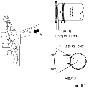
Breather Hose Installation Note
1. Install the breather hose as shown in the figure.
LF
am3zzw00005194
|
L5
am3zzw00008558
|
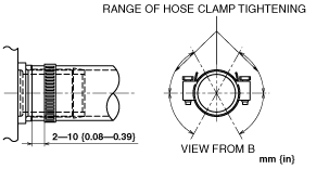
Joint Hose Installation Note
1. Install the joint hose and clamp as shown in the figure.
LF
am3zzw00005195
|
L5
am3zzw00011136
|