DTC U0125:00/U0125:88 [DYNAMIC STABILITY CONTROL (DSC)]


id0402b2879000

Note
•  Only vehicles with combined sensor.
Applied VIN (assumed):
European (L.H.D. U.K.) specs.
•  JMZ BL12F60# 100001—181415
•  JMZ BL12F70# 100001—181415
•  JMZ BL12Y20# 100001—181415
•  JMZ BL12Z20# 100001—181415
•  JMZ BL12Z50# 100001—181415
•  JMZ BL14F60# 100001—181415
•  JMZ BL14F70# 100001—181415
•  JMZ BL14Y20# 100001—181415
•  JMZ BL14Z20# 100001—181415
•  JMZ BL14Z50# 100001—181415
•  JMZ BLA2A60# 100001—181415
•  JMZ BLA2C60# 100001—181415
•  JMZ BLA2F70# 100001—181415
•  JMZ BLA2G60# 100001—181415
•  JMZ BLA2Y60# 100001—181415
•  JMZ BLA2Z20# 100001—181415
•  JMZ BLA2Z50# 100001—181415
•  JMZ BLA4360# 100001—181415
•  JMZ BLA4A60# 100001—181415
•  JMZ BLA4C60# 100001—181415
•  JMZ BLA4F70# 100001—181415
•  JMZ BLA4G60# 100001—181415
•  JMZ BLA4Y60# 100001—181415
•  JMZ BLA4Z20# 100001—181415
•  JMZ BLA4Z50# 100001—181415
Australian specs.
•  JM0 BL103100 100001—225632
•  JM0 BL10C100 100001—225632
•  JM0 BL10F100 100001—225632
•  JM0 BL10L100 100001—225632
General (R.H.D.) specs.
•  JM6 BL1031*0 100001—225632
•  JM6 BL1051*0 100001—225632
•  JM6 BL10F1*0 100001—225632
•  JM6 BL10L1*0 100001—225632
•  JM6 BL10Z1*0 100001—225632
General (L.H.D.) specs., Arab Gulf Cooperation Council, China
•  JM7 BL04F**# 100001—225632
•  JM7 BL04Z**# 100001—225632
•  JM7 BL12F**# 100001—225632
•  JM7 BL12Z**# 100001—225632
•  JM7 BL14F**# 100001—225632
•  JM7 BL14Z**# 100001—225632
•  JM7 BL22F**# 100001—225632
•  JM7 BL22Z**# 100001—225632
•  JM7 BL24F**# 100001—225632
•  JM7 BL24Z**# 100001—225632

DTC
U0125:00, U0125:88
Combined sensor system (CAN2 line malfunction)
DETECTION CONDITION
•  U0125:00
―  The signal from the combined sensor is not within specification.
•  U0125:88
―  Open or short circuit in CAN system wiring harness is detected.
POSSIBLE CAUSE
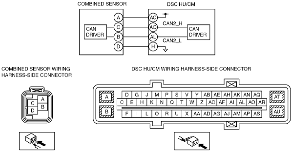
•  Open or short circuit in the CAN2_L wiring harness between combined sensor terminal B and DSC HU/CM terminal AL
•  Open or short circuit in the CAN2_H wiring harness between combined sensor terminal C and DSC HU/CM terminal AO
•  Combined sensor malfunction
•  DSC HU/CM malfunction
•  Poor connection at connectors (female terminal)

Diagnostic procedure

STEP

INSPECTION

ACTION

1
INSPECT COMBINED SENSOR SIGNAL (CAN2 LINE) FOR OPEN CIRCUIT
•  Disconnect the DSC HU/CM connectors.
•  Disconnect the combined sensor connectors.
•  Inspect for continuity between the following DSC HU/CM connectors (vehicle harness-side) and the combined sensor connector terminals (vehicle harness-side):
―  Combined sensor (CAN2_L): AL—B
―  Combined sensor (CAN2_H): AO—C
•  Is there continuity?
Yes
Go to the next step.
No
Repair or replace the wiring harness, then go to Step 4.
2
INSPECT COMBINED SENSOR SIGNAL (CAN2 LINE) FOR SHORT CIRCUIT
•  Inspect for continuity between the following DSC HU/CM connector terminals (vehicle harness-side) and body ground:
―  Combined sensor (CAN2_L): B
―  Combined sensor (CAN2_H): C
•  Is there continuity?
Yes
Repair or replace the wiring harness, then go to Step 4.
No
Go to the next step.
3
INSPECT THE COMBINED SENSOR
•  Reconnect all disconnected connectors.
•  Inspect the combined sensor.
•  Is the combined sensor normal?
Yes
Go to the next step.
No
Replace the combined sensor, then go to the next step.
4
VERIFY THAT THE SAME DTC IS NOT PRESENT
•  Clear the DTCs from the memory.
•  Are the same DTCs present?
Yes
Repeat the inspection from Step 1.
If the malfunction recurs, replace the DSC HU/CM, then go to the next step.
No
Go to the next step.
5
VERIFY THAT NO OTHER DTCS ARE PRESENT
•  Are any other DTCs output?
Yes
Go to the applicable DTC inspection.
No
DTC troubleshooting completed.