CENTER ROOF ANTENNA INSPECTION
id092000801700
-
Note
-
• The center roof antenna has a built-in antenna amplifier.
Feeder Line Inspection
1. Disconnect the negative battery cable.
2. Remove the following parts:
- (1) Sunroof seaming welt (vehicles with sunroof)
- (2) A-pillar trim (See A-PILLAR TRIM REMOVAL/INSTALLATION.)
- (3) Front scuff plate (See FRONT SCUFF PLATE REMOVAL/INSTALLATION.)
- (4) Rear scuff plate (See REAR SCUFF PLATE REMOVAL/INSTALLATION.)
- (5) B-pillar lower trim (See B-PILLAR LOWER TRIM REMOVAL/INSTALLATION.)
- (6) Upper anchor of the front seat belt (See FRONT SEAT BELT REMOVAL/INSTALLATION.)
- (7) B-pillar upper trim (See B-PILLAR UPPER TRIM REMOVAL/INSTALLATION.)
- (8) Rear seat cushion (See REAR SEAT CUSHION REMOVAL/INSTALLATION.)
- (9) Tire house trim (See TIRE HOUSE TRIM REMOVAL/INSTALLATION.)
- (10) Trunk side upper trim (See TRUNK SIDE UPPER TRIM REMOVAL/INSTALLATION.)
- (11) C-pillar trim (See C-PILLAR TRIM REMOVAL/INSTALLATION.)
- (12) Map light (See MAP LIGHT REMOVAL/INSTALLATION.)
- (13) Sunvisor (See SUNVISOR REMOVAL/INSTALLATION.)
- (14) Assist handle (See ASSIST HANDLE REMOVAL/INSTALLATION.)
- (15) Headliner (See HEADLINER REMOVAL/INSTALLATION.)
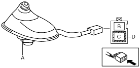
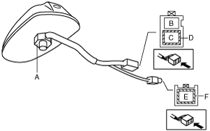
3. Verify that there is no continuity between the center roof antenna terminals A and C using an ohmmeter.
AM/FM type
AM/FM/GPS type
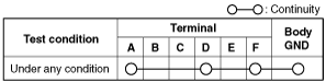
4. Inspect for continuity between the center roof antenna terminals using an ohmmeter.
-
• If not as indicated in the table, retighten nut and antenna rod. Go to the antenna amplifier inspection.
AM/FM type
AM/FM/GPS type
Antenna Amplifier Inspection
1. Connect the negative battery cable.
2. Switch the ignition to ON.
3. Turn the audio unit power to ON.
4. Tune in the radio.
5. Verify that voltage is B+ at the antenna amplifier terminal B.
AM/FM type
AM/FM/GPS type
-
• If the battery voltage cannot be verified, go to the radio troubleshooting of No.2 or No.3.
• If the battery voltage can be verified, replace the roof antenna.