|
1
|
VERIFY FREEZE FRAME DATA HAS BEEN RECORDED
• Has FREEZE FRAME DATA been recorded?
|
Yes
|
Go to the next step.
|
|
No
|
Record the FREEZE FRAME DATA on the repair order, then go to the next step.
|
|
2
|
VERIFY RELATED SERVICE INFORMATION AVAILABILITY
• Verify related Service Information availability.
• Is any related Service Information available?
|
Yes
|
Perform repair or diagnosis according to the available Service Information.
• If the vehicle is not repaired, go to the next step.
|
|
No
|
Go to the next step.
|
|
3
|
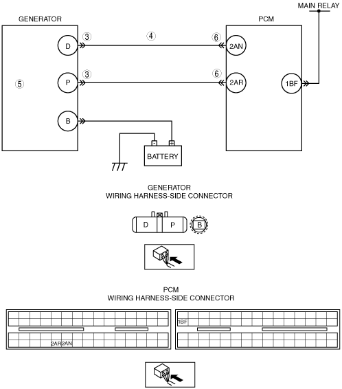
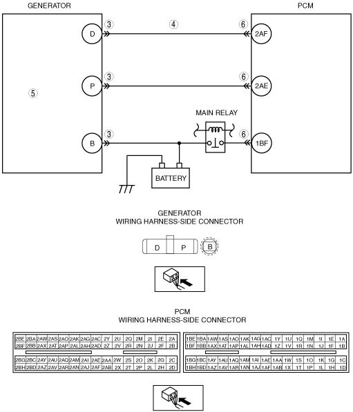
INSPECT GENERATOR CONNECTOR FOR POOR CONNECTION
• Turn the ignition switch off.
• Disconnect the generator connector.
• Inspect for poor connection (such as damaged/pulled-out pins, corrosion).
• Is there any malfunction?
|
Yes
|
Repair or replace the terminal, then go to Step 7.
|
|
No
|
Go to the next step.
|
|
4
|
INSPECT GENERATOR CONTROL TERMINAL FOR SHORT TO POWER SUPPLY
• Turn the ignition switch to the ON position (Engine off).
• Measure the voltage between generator terminal D (wiring harness-side) and body ground.
• Is the voltage B+?
|
Yes
|
Repair or replace the wiring harness for a possible short to power supply, then go to Step 7.
|
|
No
|
Go to the next step.
|
|
5
|
INSPECT BATTERY
• Is there any malfunction?
|
Yes
|
Replace the battery, then go to Step 7.
|
|
No
|
Go to the next step.
|
|
6
|
INSPECT PCM CONNECTOR FOR POOR CONNECTION
• Turn the ignition switch off.
• Disconnect the PCM connector.
• Inspect for poor connection (such as damaged/pulled-out pins, corrosion).
• Is there any malfunction?
|
Yes
|
Repair or replace the terminal, then go to next step.
|
|
No
|
Go to the next step.
|
|
7
|
VERIFY TROUBLESHOOTING OF DTC P2504 COMPLETED
• Make sure to reconnect all disconnected connectors.
• Clear the DTC from the PCM memory using the .
• Perform the “KOER self-test”.
• Is the DTC P2504 present?
|
Yes
|
Replace the PCM, then go to the next step.
|
|
No
|
Go to the next step.
|
|
8
|
VERIFY AFTER REPAIR PROCEDURE
• Perform the “AFTER REPAIR PROCEDURE”.
• Are any DTCs present?
|
Yes
|
Go to the applicable DTC inspection.
|
|
No
|
DTC troubleshooting completed.
|