 |
am3zzw00001379
CYLINDER HEAD GASKET REPLACEMENT [MZ-CD 1.6 (Y6)]
id0110b2800700
1. Drain the engine coolant. (See ENGINE COOLANT REPLACEMENT [MZ-CD 1.6 (Y6)].)
2. Remove the following parts:
3. Disconnect the coolant reserve tank hose, upper radiator hose, heater hose and ECT sensor electrical connector. (See THERMOSTAT REMOVAL/INSTALLATION [MZ-CD 1.6 (Y6)].)
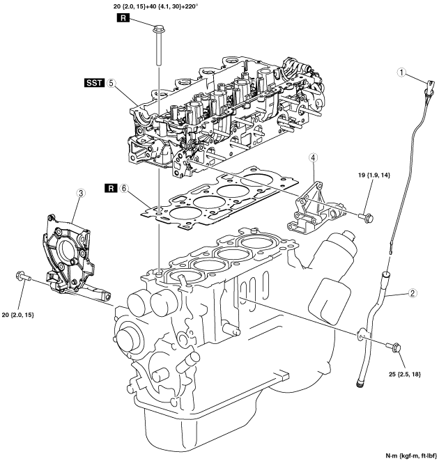
4. Remove in the order indicated in the table.
5. Install in the reverse order of removal.
am3zzw00001379
|
|
1
|
Oil level gauge
|
|
2
|
Oil level gauge pipe
|
|
3
|
Fuel pump bracket
|
|
4
|
Generator bracket
|
|
5
|
Cylinder head (See Cylinder Head Removal Note.) (See Cylinder Head Installation Note.)
|
|
6
|
Cylinder head gasket (See Cylinder Head Gasket Installation Note.)
|
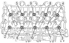
Cylinder Head Removal Note
1. Loosen the cylinder head bolts in 2—3 passes in the order shown in the figure.
am3zzw00001380
|
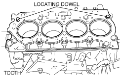
Cylinder Head Gasket Installation Note
|
Number of teeth |
Piston protrusion |
Gasket thickness |
|---|---|---|
|
1
|
0.7760—0.8250 mm {0.03056—0.03248 in}
|
1.35 mm {0.0531 in}
|
|
2
|
0.6175—0.7250 mm {0.02432—0.02854 in}
|
1.25 mm {0.0492 in}
|
|
3
|
0.7260—0.7750 mm {0.02859—0.03051 in}
|
1.30 mm {0.0512 in}
|
|
4
|
0.8260—0.8750 mm {0.03252—0.03444 in}
|
1.40 mm {0.0551 in}
|
|
5
|
0.8760—0.9830 mm {0.03449—0.03870 in}
|
1.45 mm {0.0571 in}
|
1. Install a new cylinder head gasket.
am3zzw00001381
|
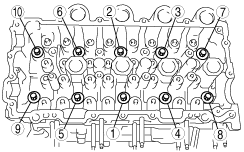
Cylinder Head Installation Note
1. Tighten the new cylinder head installation bolts using the SST (49 D032 316) in three steps in the order shown in the figure.
am3zzw00001382
|