|
am3zzw00004554
EXHAUST SYSTEM REMOVAL/INSTALLATION [L3 Turbo]
id0115b4800200
1. Remove the battery cover. (SeeBATTERY REMOVAL/INSTALLATION [L3 Turbo].)
2. Disconnect the negative battery cable.
3. Remove the charge air cooler. (See INTAKE-AIR SYSTEM REMOVAL/INSTALLATION [L3 Turbo])
4. Remove in the order indicated in the table.
5. Install in the reverse order of removal.
am3zzw00004554
|
|
1
|
Tunnel member
|
|
2
|
Member
|
|
3
|
TWC
(See TWC Removal Note.)
|
|
4
|
Seal ring (TWC side)
(See Seal Ring Removal Note.)
|
|
5
|
Seal ring (WU-TWC side)
(See Silencer Removal Note.)
|
|
6
|
HO2S
|
|
7
|
Silencer
(See Silencer Removal Note.)
|
|
8
|
Exhaust manifold insulator (Upper)
|
|
9
|
Insulator
|
|
10
|
Exhaust manifold insulator (Lower)
|
|
11
|
A/F sensor
|
|
12
|
WU-TWC insulator
|
|
13
|
WU-TWC bracket
|
|
14
|
WU-TWC
(See WU-TWC Removal Note.)
(See WU-TWC Installation Note.)
|
|
15
|
Exhaust manifold
|
|
16
|
Exhaust manifold gasket
|
TWC Removal Note
1. Disconnect the hanger rubber except for the one installed to the rear end of the vehicle from the silencer, and suspend the silencer using rope.
am3zzw00003471
|
2. Remove the TWC.
Seal Ring Removal Note
1. Remove the seal ring using a flathead screwdriver being careful not to damage the pipe.
acxaaw00000754
|
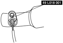
A/F Sensor, HO2S Removal Note
1. Remove the A/F sensor, HO2S using the SST before removing the exhaust manifold.
ampjjw00001053
|
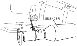
Silencer Removal Note
1. Remove the rear shock absorber lower bolts. (See REAR SHOCK ABSORBER REMOVAL/INSTALLATION.)
2. Loosen the rear crossmember component installation bolts (6 locations) and lower the rear crossmember component approx. 70 mm {2.8 in}. (See REAR CROSSMEMBER REMOVAL/INSTALLATION.)
3. Remove the main silencer.
Exhaust Manifold Insulator (Upper) Removal Note
1. Remove the charge air cooler bracket.
2. Remove the exhaust manifold insulator (upper)
Insulator Removal Note (R.H.D.)
1. Remove the cooler hose (LO) installation nut and set it out of the way. (See REFRIGERANT LINE REMOVAL/INSTALLATION [L3 Turbo].)
2. Remove the power steering reserve tank installation bolt and set it out of the way. (See POWER STEERING OIL PUMP REMOVAL/INSTALLATION [L3 Turbo].)
3. Detach the cooler pipe No.3 installation clips and set the cooler pipe No.3 out of the way. (See REFRIGERANT LINE REMOVAL/INSTALLATION [L3 Turbo].)
4. Disconnect the brake vacuum hose.
5. Remove the insulator.
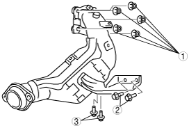
WU-TWC Removal Note
1. Set the generator duct out of the way. (See GENERATOR REMOVAL/INSTALLATION [L3 Turbo].)
am3zzw00004556
|
2. Remove the WU-TWC.
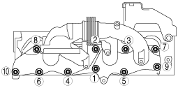
Exhaust Manifold Installation Note
1. Tighten the exhaust manifold installation nuts in the order shown.
acxuuw00000175
|
WU-TWC Installation Note
1. Temporarily tighten No.1 shown in the figure.
am3zzw00004555
|
2. Temporarily tighten No.2 shown in the figure.
3. Temporarily tighten No.3 shown in the figure.
4. Completely tighten No.1 shown in the figure.
5. Completely tighten No.2 shown in the figure.
6. Completely tighten No.3 shown in the figure.
Seal Ring (WU-TWC Side) Installation Note
1. Temporarily install the seal ring to the pipe so that the seal ring is even with the flange.
acxaaw00000755
|
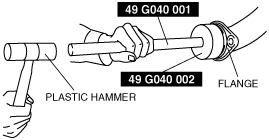
2. Install the SST to the seal ring so that the SST is even with the flange.
acxaaw00000756
|
3. Press in the seal ring by tapping the SST using a plastic hammer until the seal ring contacts the flange.
acxaaw00000757
|
Seal Ring (TWC Side) Installation Note
1. Temporarily install the seal ring to the pipe so that the seal ring is even with the flange.
acxaaw00000755
|
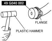
2. Install the SST to the seal ring so that the SST is even with the flange.
am3zzw00004575
|
3. Press in the seal ring by tapping the SST using a plastic hammer until the seal ring contacts the flange.
am3zzw00004576
|