THROTTLE POSITION (TP) SENSOR INSPECTION[ZJ, ZY, Z6]
id0140b1802700
-
Note
-
• Before performing the following inspection, make sure to follow the procedure as indicated in the troubleshooting flowchart. (See
HOW TO USE THIS MANUAL.)
Without Throttle Valve Actuator
Resistance inspection
1. Verify the following.
-
• Throttle valve closed status
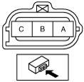
2. Disconnect the TP sensor connector.
3. Verify that the resistance between terminals B and C changes moderately corresponding to the throttle valve openings.
-
• If the resistance change is verified, go to the next step.
4. Measure the resistance between terminals A and B.
-
• If the monitor item condition/specification (reference) is not within the specification, even though there is no malfunction, perform the “Circuit Open/Short Inspection”.
-
TP sensor resistance
-
2.5—6.0 kilohms [25 °C {77 °F}]
Circuit open/short inspection
1. Remove the PCM connector cover.
2. Disconnect the PCM connector. (See INTAKE-AIR SYSTEM REMOVAL/INSTALLATION[ZJ, ZY, Z6].)
3. Inspect the following wiring harness for open or short circuit (continuity check).
-
Open circuit
-
• If there is no continuity, there is an open circuit. Repair or replace the wiring harness.
-
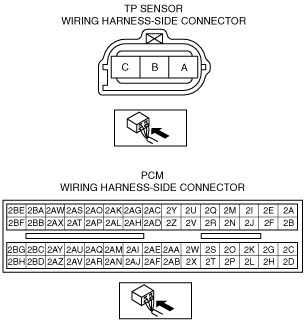
― TP sensor terminal A and PCM terminal 2W
― TP sensor terminal B and PCM terminal 2AE
― TP sensor terminal C and PCM terminal 2AA
-
Short circuit
-
• If there is continuity, there is a short circuit. Repair or replace the wiring harness.
-
― TP sensor terminal A and body ground
― TP sensor terminal B and power supply
― TP sensor terminal C and power supply
― TP sensor terminal C and body ground
With Throttle Valve Actuator
-
Caution
-
• This inspection procedure cannot be completed correctly if the APP sensor has a malfunction. Before performing this procedure, verify that any one of the DTCs related to the APP sensor is not detected.
Voltage inspection
1. Turn the ignition switch to the ON position.
2. Verify that the TP sensor output voltage (M-MDS PID: TP1, TP2) is within the specification. (See PCM INSPECTION[ZJ, ZY, Z6].)
-
• If the monitor item condition/specification (reference) is not within the specification, even though there is no malfunction, perform the “Circuit Open/Short Inspection”.
Circuit open/short inspection
1. Remove the PCM connector cover.
2. Disconnect the PCM connector. (See INTAKE-AIR SYSTEM REMOVAL/INSTALLATION[ZJ, ZY, Z6].)
3. Disconnect the throttle body connector.
4. Inspect the following wiring harnesses for open or short circuit. (Continuity inspection)
-
Open circuit
-
• If there is no continuity in the following wiring harnesses, there is an open circuit. Repair or replace the wiring harness.
-
― Throttle body terminal C and PCM terminal 2AW
― Throttle body terminal D and PCM terminal 2AT
― Throttle body terminal E and PCM terminal 2AS
― Throttle body terminal F and PCM terminal 2AX
-
Short circuit
-
• If there is continuity in the following wiring harnesses, there is a short circuit. Repair or replace the wiring harness.
-
― Throttle body terminal C and body ground
― Throttle body terminal C and power supply
― Throttle body terminal E and body ground
― Throttle body terminal E and power supply
― Throttle body terminal F and body ground
― Throttle body terminal F and power supply
― Throttle body terminal D and body ground
― Throttle body terminal D and power supply