 |
am3zzw00001688
ON-BOARD DIAGNOSIS [ABS]
id0402a7805500
On-Board Diagnostic (OBD) Test Description
Read/clear diagnostic results
PID/Data monitor and record
Active command modes
Reading DTCs Procedure
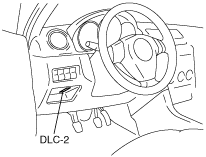
1. Connect the M-MDS to the DLC-2 connector.
am3zzw00001688
|
2. After the vehicle is identified, select the following items from the initial screen of the M-MDS.
3. Verify the DTC according to the directions on the screen.
4. After completion of repairs, clear all DTCs stored in the DSC. (See Clearing DTCs Procedures.)
Clearing DTCs Procedures
1. Connect the M-MDS to the DLC-2 connector.
am3zzw00001688
|
2. After the vehicle is identified, select the following items from the initial screen of the M-MDS.
3. Verify the DTC according to the directions on the screen.
4. Press the clear button on the DTC screen to clear the DTC.
5. Verify that no DTCs are displayed.
PID/Data Monitor and Record Procedure
1. Connect the M-MDS to the DLC-2 connector.
am3zzw00001688
|
2. After the vehicle is identified, select the following items from the initial screen of the M-MDS.
3. Select the applicable PID from the PID table.
4. Verify the PID data according to the directions on the screen.
Active Command Modes Procedure
1. Connect the M-MDS to the DLC-2 connector.
am3zzw00001688
|
2. After the vehicle is identified, select the following items from the initial screen of the M-MDS.
3. Select the active command modes from the PID table.
4. Perform the active command modes, inspect the operations for each parts.
DTC Table
|
DTC |
System malfunction location |
Page |
|---|---|---|
|
M-MDS |
||
|
B1317
|
Power supply system
|
(See DTC B1317, B1318 [ABS].)
|
|
B1318
|
Power supply system
|
(See DTC B1317, B1318 [ABS].)
|
|
B1342
|
ABS CM (internal malfunction)
|
(See DTC B1342, C1267 [ABS].)
|
|
C1095
|
Pump motor, motor relay
|
(See DTC C1095 [ABS].)
|
|
C1141
|
LF ABS sensor rotor
|
|
|
C1142
|
RF ABS sensor rotor
|
|
|
C1143
|
LR ABS sensor rotor
|
|
|
C1144
|
RR ABS sensor rotor
|
|
|
C1145
|
RF ABS wheel-speed sensor
|
|
|
C1155
|
LF ABS wheel-speed sensor
|
|
|
C1165
|
RR ABS wheel-speed sensor
|
|
|
C1175
|
LR ABS wheel-speed sensor
|
|
|
C1233
|
LF ABS wheel-speed sensor/ABS sensor rotor
|
|
|
C1234
|
RF ABS wheel-speed sensor/ABS sensor rotor
|
|
|
C1235
|
RR ABS wheel-speed sensor/ABS sensor rotor
|
|
|
C1236
|
LR ABS wheel-speed sensor/ABS sensor rotor
|
|
|
C1267
|
ABS HU/CM (internal malfunction)
|
(See DTC B1342, C1267 [ABS].)
|
|
C1446
|
Brake switch
|
|
|
U1900
|
CAN line
|
(See DTC U1900, U2012 [ABS].)
|
|
U2012
|
CAN line
|
(See DTC U1900, U2012 [ABS].)
|
PID/DATA Monitor Table
|
PID name (definition) |
Unit/Condition |
Operation condition (reference) |
Action |
ABS HU/CM terminal |
|---|---|---|---|---|
|
BOO_ABS
(Brake pedal switch input)
|
On/Off
|
• Brake pedal depressed: On
• Brake pedal released: Off
|
Inspect the brake switch.
|
—
|
|
CCNTABS
(Number of continuous codes)
|
—
|
• DTCs detected:
1—255
• No DTCs detected: 0
|
Perform the DTC inspection.
(See DTC Table.)
|
—
|
|
LF_WSPD
(Left front ABS wheel-speed sensor input)
|
KPH, MPH
|
• Vehicle stopped: 0 KPH, 0 MPH
• Vehicle running: Vehicle speed
|
Inspect the ABS wheel-speed sensor.
|
I, K
|
|
LR_WSPD
(Left rear ABS wheel-speed sensor input)
|
KPH, MPH
|
• Vehicle stopped: 0 KPH, 0 MPH
• Vehicle running: Vehicle speed
|
Inspect the ABS wheel-speed sensor.
|
U, W
|
|
RF_WSPD
(Right front ABS wheel-speed sensor input)
|
KPH, MPH
|
• Vehicle stopped: 0 KPH, 0 MPH
• Vehicle running: Vehicle speed
|
Inspect the ABS wheel-speed sensor.
|
Q, O
|
|
RR_WSPD
(Right rear ABS wheel-speed sensor input)
|
KPH, MPH
|
• Vehicle stopped: 0 KPH, 0 MPH
• Vehicle running: Vehicle speed
|
Inspect the ABS wheel-speed sensor.
|
E, C
|
Active Command Modes Table
|
Command name |
Output part |
Operation |
Operating condition |
|---|---|---|---|
|
PMP_MOTOR
|
Pump motor
|
On/Off
|
Ignition switch at ON
|
|
RF_OUTLET
|
RF outlet solenoid valve
|
||
|
RF_INLET
|
RF inlet solenoid valve
|
||
|
LF_OUTLET
|
LF outlet solenoid valve
|
||
|
LF_INLET
|
LF inlet solenoid valve
|
||
|
RR_OUTLET
|
RR outlet solenoid valve
|
||
|
RR_INLET
|
RR inlet solenoid valve
|
||
|
LR_OUTLET
|
LR outlet solenoid valve
|
||
|
LR_INLET
|
LR inlet solenoid valve
|