|
1
|
INSPECT PID FOR ABS WHEEL-SPEED SENSOR OUTPUT ERROR USING M-MDS
• Turn the ignition switch off.
• Connect the M-MDS to the DLC-2.
• Select the following PIDs using the M-MDS: LF_WSPD
LR_WSPD
RF_WSPD
RR_WSPD
• Drive the vehicle.
• Verify that the vehicle speeds detected by the four ABS wheel-speed sensors are approximately the same.
• Are the vehicle speeds approximately the same?
|
Yes
|
Go to Step 3.
|
|
No
|
Go to the next step.
|
|
2
|
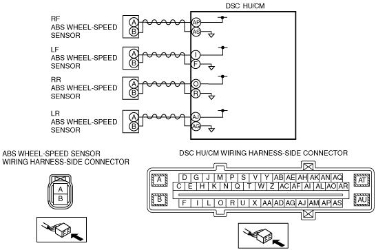
INSPECT ABS WHEEL-SPEED SENSOR CONNECTOR FOR SHORT TO GROUND
• Disconnect the ABS wheel-speed sensor connectors.
• Verify that there is no continuity between the following ABS wheel-speed sensor terminals (vehicle harness-side) and body ground.
-
― ABS wheel-speed sensor (RF): B—Body ground
― ABS wheel-speed sensor (LF): B—Body ground
― ABS wheel-speed sensor (RR): B—Body ground
― ABS wheel-speed sensor (LR): B—Body ground
• Is the continuity normal?
|
Yes
|
Go to the next step.
|
|
No
|
Repair or replace the wiring harness, then go to Step 5.
|
|
3
|
INSPECT IF MALFUNCTION OCCURRED DUE TO IMPROPER SENSOR CLEARANCE.
• Inspect the clearance between the ABS wheel-speed sensor and the ABS sensor rotor.
• Is the clearance normal?
-
ClearanceFront:2.1 mm {0.082 in} or less
Rear:1.46 mm {0.057 in} or less
|
Yes
|
Go to the next step.
|
|
No
|
Replace the ABS wheel-speed sensor, then go to Step 5.
|
|
4
|
VISUALLY INSPECT ABS SENSOR ROTOR FOR FOREIGN MATERIAL ADHERING OR IMPROPER INSTALLATION
• Is the result normal?
|
Yes
|
Go to the next step.
|
|
No
|
Replace the wheel hub component, then go to the next step.
|
|
5
|
VERIFY THAT THE SAME DTC IS NOT PRESENT
• Clear the DTCs from the memory.
• Start the engine and drive the vehicle at 10 km/h {6.2 mph} or more.
• Are the same DTCs present?
|
Yes
|
Repeat the inspection from Step 1.
If the malfunction recurs, replace the DSC CM.
|
|
No
|
Go to the next step.
|
|
6
|
VERIFY THAT NO OTHER DTCS ARE PRESENT
• Are any other DTCs output?
|
Yes
|
Go to the applicable DTC inspection.
|
|
No
|
DTC troubleshooting completed.
|