STEP
INSPECTION
ACTION
1
INSPECT ABS HU/CM POWER SUPPLY FUSE
• Is the ABS HU/CM ignition power supply fuse normal?
Yes
Go to the next step.
Inspect for a short to ground on blown fuse’s circuit.
No
Repair or replace if necessary.
Install appropriate amperage fuse.
2
INSPECT WIRING HARNESS BETWEEN ABS HU/CM AND DLC‐2 FOR CONTINUITY AND SHORT CIRCUIT
• Perform DTC inspection.
• Is any error message displayed regarding communication between the ABS HU/CM and M-MDS?
Yes
If the communication error message is displayed even after inspecting according to the procedure displayed on the M-MDS, go to step 6.
No
Go to the next step.
3
INSPECT FOR DTCs IN ABS HU/CM
• Have DTCs been stored in memory?
Yes
Perform the applicable DTC inspection.
(See ON-BOARD DIAGNOSIS [ABS].)
No
Inspect the instrument cluster.
If the instrument cluster is normal, go to the next step.
If the instrument cluster has some malfunction, repair the instrument cluster, then go to the next step.
4
INSPECT BATTERY
• Is the battery voltage normal?
Yes
Go to the next step.
No
Inspect the battery and charging system.
(See BATTERY INSPECTION [LF, L3].)
5
INSPECT CHARGING SYSTEM
• Is the battery voltage normal with electrical load (such as A/C, headlight) on and engine idling?
Yes
Go to the next step.
No
Inspect the charging system (such as drive belt tension and generator).
6
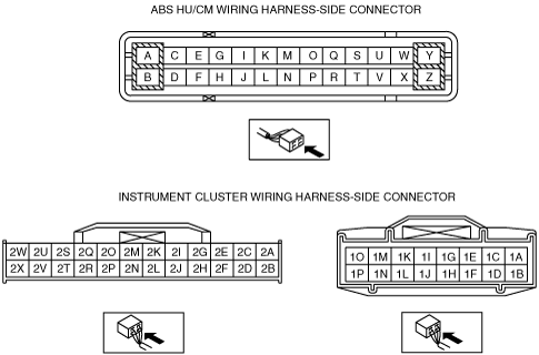
INSPECT ABS HU/CM IGNITION POWER SUPPLY SYSTEM (TERMINAL N)
• Disconnect the ABS HU/CM connector.
• Turn the ignition switch to the ON position.
• Inspect the voltage of connector terminal N.
Specification: approx. 8 V
• Is the voltage within the specification?
Yes
Replace the ABS CM (open or short in ground circuit in the ABS CM).
No
Repair the wiring harness between the ABS HU/CM and ground.
7
INSPECT WIRING HARNESS BETWEEN ABS HU/CM GROUND FOR CONTINUITY
• Turn the ignition switch to the LOCK position.
• Is there continuity between connector terminal B and ground?
Yes
If a malfunction error message is displayed on the M-MDS in Step 1 inspection, go to the next step.
If a malfunction error message is not displayed on the M-MDS in Step 1 inspection, troubleshooting is completed.
No
Repair the wiring harness between the ABS HU/CM and ground.
8
INSPECT WIRING HARNESS BETWEEN ABS HU/CM AND DLC-2 FOR CONTINUITY
• Is there continuity between connector terminal H, L and DLC-2?
Yes
Go to the next step.
No
Repair the wiring harness between the ABS HU/CM and DLC-2.
9
INSPECT WIRING HARNESS BETWEEN ABS HU/CM AND DLC-2 FOR SHORT TO POWER SUPPLY
• Is the voltage approx. 12 V at connector terminal H, L?
Yes
Repair the wiring harness between the ABS HU/CM and DLC-2.
No
Go to the next step.
10
INSPECT WIRING HARNESS BETWEEN ABS HU/CM AND DLC-2 FOR SHORT TO GROUND
• Is there continuity between connector terminal H, L and DLC-2?
Yes
Repair the wiring harness between the ABS HU/CM and DLC-2.
No
Replace the ABS CM (communication circuit malfunction in ABS CM).