 |
am3zzw00001707
ON-BOARD DIAGNOSIS [ELECTRO HYDRAULIC POWER ASSIST STEERING (EHPAS)]
id0602b1801500
On-Board Diagnostic (OBD) Test Description
Read/clear diagnostic results
PID/Data monitor and record
Reading DTCs Procedure
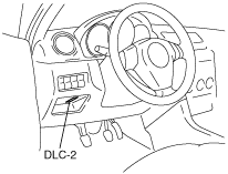
1. Connect the M-MDS to the DLC-2 connector.
am3zzw00001707
|
2. After the vehicle is identified, select the following items from the initial screen of the M-MDS.
3. Verify the DTC according to the directions on the screen.
4. After completion of repairs, clear all DTCs stored in the DSC. (See ON-BOARD DIAGNOSIS [ELECTRO HYDRAULIC POWER ASSIST STEERING (EHPAS)].)
Clearing DTCs Procedure
1. Connect the M-MDS to the DLC-2 connector.
am3zzw00001707
|
2. After the vehicle is identified, select the following items from the initial screen of the M-MDS.
3. Verify the DTC according to the directions on the screen.
4. Press the clear button on the DTC screen to clear the DTC.
5. Verify that no DTCs are displayed.
PID/Data Monitor and Record Procedure
1. Connect the M-MDS to the DLC-2 connector.
am3zzw00001707
|
2. After the vehicle is identified, select the following items from the initial screen of the M-MDS.
3. Select the applicable PID from the PID table.
4. Verify the PID data according to the directions on the screen.
DTC Table
|
DTC |
Diagnosis system component |
Page |
|---|---|---|
|
M-MDS |
||
|
B1238
|
EHPAS control module
|
|
|
B1317
|
Battery power supply
|
|
|
B1318
|
Battery power supply
|
|
|
B1342
|
EHPAS control module
|
|
|
B1352
|
Ignition power supply
|
|
|
B2477
|
EHPAS control module configuration
|
|
|
C1099
|
Electric power steering oil pump (motor)
|
|
|
C1278
|
Steering angle sensor
|
|
|
U0073
|
CAN bus communication error
|
|
|
U0100
|
Lost communication with the PCM
|
|
|
U2023
|
Fault received from other modules
|
PID/DATA Monitor Table
|
PID Name (Definition) |
Unit/ Condition |
Condition/Specification |
Action |
EHPAS control module terminal |
|---|---|---|---|---|
|
BOARD_T
(Printed circuit board temperature)
|
°C, °F
|
• Indicates circuit temperature.
|
Replace the EHPAS control module. (See ELECTRIC POWER STEERING OIL PUMP COMPONENT REMOVAL/INSTALLATION [ZY, LF, L3, MZ-CD 1.6 (Y6)].)
|
—
|
|
CCNT
(Number of continuous codes)
|
—
|
• DTCs are detected: 1—255
• No DTCs are detected: 0
|
Perform inspection using appropriate DTC.
|
—
|
|
ENGRPM
(Engine speed signal)
|
RPM
|
• Engine speed 1,000 rpm: 1000 RPM
|
Inspect the PCM. (See PCM INSPECTION [LF, L3].) (See PCM INSPECTION [MZ-CD 1.6 (Y6)].) (See PCM INSPECTION [ZJ, ZY, Z6].)
|
—
|
|
MTR_AMP
(Pump Motor Operation Current)
|
A
|
• Indicates pump motor operation current.
|
Replace the EHPAS control module. (See ELECTRIC POWER STEERING OIL PUMP COMPONENT REMOVAL/INSTALLATION [ZY, LF, L3, MZ-CD 1.6 (Y6)].)
|
—
|
|
RPM_ACT
(Actual pump motor revolution per minutes)
|
RPM
|
• Indicates pump motor revolution per minutes.
|
Replace the EHPAS control module. (See ELECTRIC POWER STEERING OIL PUMP COMPONENT REMOVAL/INSTALLATION [ZY, LF, L3, MZ-CD 1.6 (Y6)].)
|
—
|
|
RPM_TGT
(Target pump motor revolution per minutes)
|
RPM
|
• Indicates pump motor target revolution per minutes.
|
Replace the EHPAS control module. (See ELECTRIC POWER STEERING OIL PUMP COMPONENT REMOVAL/INSTALLATION [ZY, LF, L3, MZ-CD 1.6 (Y6)].)
|
—
|
|
STEER_RATE
(Steering wheel rotation rate)
|
°/s
|
• Indicates steering wheel rotation rate.
|
Inspect steering angle sensor. (See STEERING ANGLE SENSOR INSPECTION.)
|
3B, 3D
|
|
VPWR
(Module supply voltage)
|
V
|
• IG switch ON: B+
|
Inspect the battery. (SeeBATTERY INSPECTION [LF, L3].) (See BATTERY INSPECTION [MZ-CD 1.6 (Y6)].) (See BATTERY INSPECTION [ZJ, ZY, Z6].)
Inspect power supply circuit (such as IG switch, fuse).
|
1B, 2F
|
|
VSS
(Vehicle speed)
|
KPH/MPH
|
• Vehicle is stopped:
0 KPH/0 MPH
• Vehicle speed 20 km/h {12 mph}: 20 KPH/12 MPH
|
Inspect the PCM. (See PCM INSPECTION [LF, L3].) (See PCM INSPECTION [MZ-CD 1.6 (Y6)].) (See PCM INSPECTION [ZJ, ZY, Z6].)
|
—
|