 |
am3zzw00018424
AIR INTAKE ACTUATOR INSPECTION [FULL-AUTO AIR CONDITIONER]
id0740a1801500
With Potentiometer Type
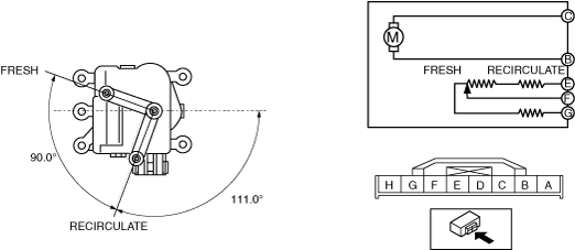
L.H.D.
1. Disconnect the negative battery cable. (See NEGATIVE BATTERY CABLE DISCONNECTION/CONNECTION [SKYACTIV-D 2.2].)(See NEGATIVE BATTERY CABLE DISCONNECTION/CONNECTION [SKYACTIV-D 1.5].)(See NEGATIVE BATTERY CABLE DISCONNECTION/CONNECTION [SKYACTIV-G 1.5, SKYACTIV-G 2.0, SKYACTIV-G 2.5].)(See NEGATIVE BATTERY CABLE DISCONNECTION/CONNECTION [MZR 1.6].)
2. Remove the glove compartment. (See GLOVE COMPARTMENT REMOVAL/INSTALLATION.)
3. Remove the following parts (with center display)(with Bluetooth® system):
4. Remove the air intake actuator. (See AIR INTAKE ACTUATOR REMOVAL/INSTALLATION [FULL-AUTO AIR CONDITIONER].)
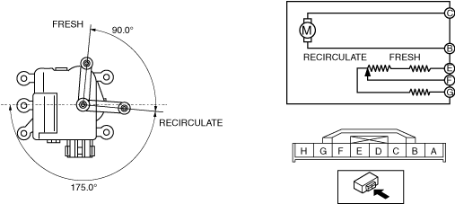
5. Apply battery positive voltage and connect the ground to the air intake actuator terminals as indicated in the table below and verify the operation condition.
|
B+ Terminal |
Ground Terminal |
Operation |
|---|---|---|
|
B
|
C
|
FRESH → RECIRCULATE
|
|
C
|
B
|
RECIRCULATE → FRESH
|
am3zzw00018424
|
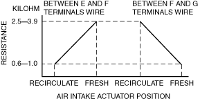
6. Verify that the resistance between terminals E and F, F and G matches the air intake actuator operation as shown in the graph.
am3zzw00019836
|
R.H.D.
1. Disconnect the negative battery cable. (See NEGATIVE BATTERY CABLE DISCONNECTION/CONNECTION [SKYACTIV-D 2.2].)(See NEGATIVE BATTERY CABLE DISCONNECTION/CONNECTION [SKYACTIV-G 1.5, SKYACTIV-G 2.0, SKYACTIV-G 2.5].)(See NEGATIVE BATTERY CABLE DISCONNECTION/CONNECTION [SKYACTIV-D 1.5].)
2. Remove the following parts:
3. Remove the air intake actuator. (See AIR INTAKE ACTUATOR REMOVAL/INSTALLATION [FULL-AUTO AIR CONDITIONER].)
4. Apply battery positive voltage and connect the ground to the air intake actuator terminals as indicated in the table below and verify the operation condition.
|
B+ Terminal |
Ground Terminal |
Operation |
|---|---|---|
|
B
|
C
|
RECIRCULATE → FRESH
|
|
C
|
B
|
FRESH → RECIRCULATE
|
am3zzw00018426
|
5. Verify that the resistance between terminals E and F, F and G matches the air intake actuator operation as shown in the graph.
am3zzw00019837
|
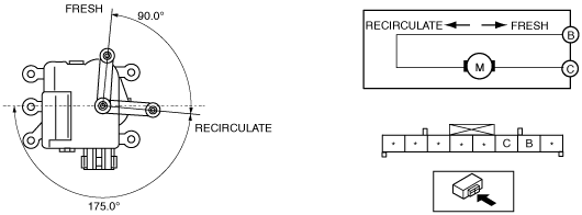
With Mechanical Lock Type
L.H.D.
1. Disconnect the negative battery cable. (See NEGATIVE BATTERY CABLE DISCONNECTION/CONNECTION [SKYACTIV-G 1.5, SKYACTIV-G 2.0, SKYACTIV-G 2.5].)(See NEGATIVE BATTERY CABLE DISCONNECTION/CONNECTION [MZR 1.6].)
2. Remove the glove compartment. (See GLOVE COMPARTMENT REMOVAL/INSTALLATION.)
3. Remove the following parts (with center display)(with Bluetooth® system):
4. Remove the air intake actuator. (See AIR INTAKE ACTUATOR REMOVAL/INSTALLATION [FULL-AUTO AIR CONDITIONER].)
5. Apply battery positive voltage and connect the ground to the air intake actuator terminals as indicated in the table below and verify the operation condition.
|
B+ Terminal |
Ground Terminal |
Operation |
|---|---|---|
|
B
|
C
|
FRESH → RECIRCULATE
|
|
C
|
B
|
RECIRCULATE → FRESH
|
am6xuw00006135
|
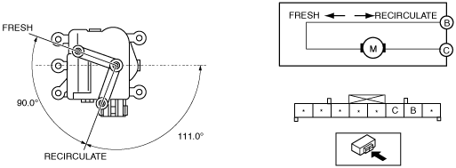
R.H.D.
1. Disconnect the negative battery cable. (See NEGATIVE BATTERY CABLE DISCONNECTION/CONNECTION [SKYACTIV-D 2.2].)(See NEGATIVE BATTERY CABLE DISCONNECTION/CONNECTION [SKYACTIV-G 1.5, SKYACTIV-G 2.0, SKYACTIV-G 2.5].)(See NEGATIVE BATTERY CABLE DISCONNECTION/CONNECTION [MZR 1.6].)
2. Remove the glove compartment. (See GLOVE COMPARTMENT REMOVAL/INSTALLATION.)
3. Remove the following parts:
4. Remove the air intake actuator. (See AIR INTAKE ACTUATOR REMOVAL/INSTALLATION [FULL-AUTO AIR CONDITIONER].)
5. Apply battery positive voltage and connect the ground to the air intake actuator terminals as indicated in the table below and verify the operation condition.
|
B+ Terminal |
Ground Terminal |
Operation |
|---|---|---|
|
B
|
C
|
RECIRCULATE → FRESH
|
|
C
|
B
|
FRESH → RECIRCULATE
|
am3zzw00015542
|