ACTIVE DRIVING DISPLAY
id092200037300
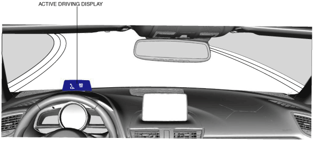
Purpose
• The active driving display displays the vehicle information in the set display within the visual range of the driver allowing verification of the vehicle information with only the slightest change in the line of vision.
Function
• The active driving display displays the following vehicle information.
-
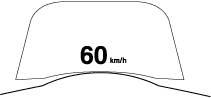
― Current vehicle speed
― Cruise control set vehicle speed (with cruise control system)
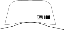
― Adjustable speed limiter set vehicle speed (with Adjustable speed limiter system)
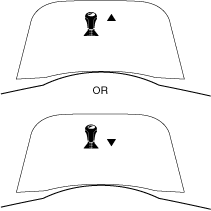
― Mazda radar cruise control (MRCC) system operation status or warning display (with MRCC)
― Smart brake support (SBS) warning display (with SBS)
― Distance recognition support system (DRSS) system operation status display (with DRSS)
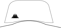
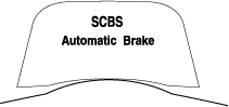
― Smart city brake support (SCBS) warning display (with SCBS)
― Lane departure warning system (LDWS) operation status or warning display (with LDWS)
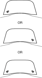
― Blind spot monitoring (BSM) system warning indication (with blind spot monitoring (BSM) system)
― Driver attention alert system warning display (with driver attention alert system)
― Lane-keep assist system operation status or warning indication (with lane-keep assist system)
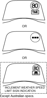
― Traffic sign recognition system (TSR) warning display (with traffic sign recognition system (TSR))
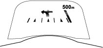
― Travel direction (turn by turn (TBT)) display (with car navigation system)
• The active driving display displays the following content based on the following CAN signals when the engine is started. Refer to reference for details on display content.
|
CAN signal sending module
|
Signal name
|
Display content
|
Display example
|
Reference
|
|
PCM
|
Vehicle speed signal
|
Current vehicle speed
|
 |
|
|
PCM
|
Cruise control set vehicle speed display signal
|
Cruise control set vehicle speed
|
 |
|
|
PCM
|
Adjustable speed limiter set vehicle speed display signal
|
Adjustable speed limiter set vehicle speed
|
 |
|
|
Radar unit (MRCC system)
|
Operation display request signal
|
Distance between vehicles and MRCC set vehicle speed
|
 |
|
|
Warning display request signal
|
Shift up/down required (MTX)
|
 |
|
MRCC automatically canceled due to low vehicle speed
|
 |
|
Deceleration exceeding system limits required
|
 |
|
Radar unit (SBS)
|
Warning display request signal
|
Deceleration exceeding system limits required
|
|
|
|
Radar unit (DRSS system)
|
Operation display request signal
|
Distance from vehicle ahead
|
 |
|
|
Forward sensing camera (FSC) (SCBS)
|
Warning display request signal
|
Warning screen
|
 |
|
|
Forward sensing camera (FSC) (LDWS)
|
Operation display request signal
|
Vehicle lane display
|
 |
|
|
Warning display request signal
|
Warning screen
|
 |
|
Forward sensing camera (FSC) ( Lane-keep assist system )
|
Operation display request signal
|
Vehicle lane display
|
|
|
|
Warning display request signal
|
Warning screen
|
|
|
Blind spot monitoring (BSM) control module
|
Warning display request signal
|
Warning screen
|
 |
|
|
Parking assist unit (Driver attention alert system)
|
Warning display request signal
|
Warning screen
|
 |
|
|
Forward sensing camera (FSC) (Traffic sign recognition system (TSR))
|
Speed limit signs
|
Warning screen
|
 |
|
|
Do not enter sign
|
Warning screen
|
 |
|
Stop sign
|
Warning screen
|
 |
|
Connectivity master unit (CMU)
|
Turn-by-turn (TBT) display request signal
|
Travel direction display
|
 |
|
Setting function
-
• The following items for the active driving display can be set on the “Settings” screen of the center display.
-
Note
-
• The indication position, brightness level, and display information of the active driving display is stored in the position memory control module during seat position programming. (With position memory system) For the seat position programming method, refer to the [POSITION MEMORY SYSTEM]. (See
POSITION MEMORY SYSTEM.)
|
Item
|
Setting contents
|
|
Height
|
The combiner open/close angle can be adjusted.
|
|
Brightness Control
|
The display brightness can be switched between automatic/manual.
|
|
Calibration
|
The automatic dimness adjustment level can be switched.
(Can only be changed when Auto is selected in the brightness control)
|
|
Brightness
|
The brightness of the display can be adjusted.
(Can only be changed when Manual is selected in the brightness control)
|
|
Navigation
|
The turn-by-turn (TBT) display can be switched on/off.
|
|
Active Driving Display
|
The active driving display can be switched between ON/OFF.
|
|
Reset
|
The active driving display setting can be changed to the initial setting.
|
Demonstration function
-
Note
-
• The demonstration function force-displays the active driving display without the engine being started, such as on an indoor exhibition vehicle, so that customers can verify the display status.
• Because the demonstration function launches the active driving display with the ignition switched ON (engine off), take measures to prevent battery discharge such as connecting an external power supply to the vehicle.
• The demonstration function launches the active driving display with the ignition switched ON (engine off) to display the vehicle information in the display.
-
Demonstration function on setting procedure
-
1. Verify that the all doors are closed.
2. After switching the ignition ON (engine off), switch the light switch within 5 s as follows.
-
• OFF→TNS (parking lights)→OFF→TNS (parking lights)→OFF→TNS (parking lights)→OFF
3. Switch the light switch (dimmer switch) within 5 s after Step 2 as follows.
-
• OFF→Headlight HI ON→OFF→Headlight HI ON→OFF→Headlight HI ON→OFF
4. Switch the light switch as follows to turn the demonstration function on.
-
• OFF→TNS (parking lights)→OFF→TNS (parking lights)→OFF→TNS (parking lights)→OFF→TNS (parking lights)→OFF→TNS (parking lights)→OFF→TNS (parking lights)→OFF→TNS (parking lights)→OFF→TNS (parking lights)
-
Note
-
• After Step 4, the combiner closes when the demonstration function turns on.
5. Switch the ignition OFF (LOCK).
-
Note
-
• If the ignition is switched OFF (LOCK) with the demonstration function turned on, the demonstration function will operate the next time the ignition is switched ON (engine off).
• If the following is performed with the demonstration function turned on, the demonstration function turns off.
-
― The battery power is interrupted or the ROOM fuse is removed.
― The vehicle is driven at 20 km/h or more.
-
Demonstration function off setting procedure
-
1. After switching the ignition ON (engine off), switch the light switch within 5 s as follows.
-
• OFF→TNS (parking lights)→OFF→TNS (parking lights)→OFF→TNS (parking lights)→OFF
2. Switch the light switch (dimmer switch) within 5 s after Step 1 as follows.
-
• OFF→Headlight HI ON→OFF→Headlight HI ON→OFF→Headlight HI ON→OFF
3. Switch the light switch as follows to turn the demonstration function off.
-
• OFF→TNS (parking lights)→OFF→TNS (parking lights)→OFF→TNS (parking lights)→OFF→TNS (parking lights)→OFF→TNS (parking lights)→OFF→TNS (parking lights)→OFF→TNS (parking lights)→OFF→TNS (parking lights)→OFF→TNS (parking lights)
-
Note
-
• After Step 3, the combiner displays "Demonstration Mode OFF" when the demonstration function turns off.
4. Switch the ignition OFF (LOCK).
Construction
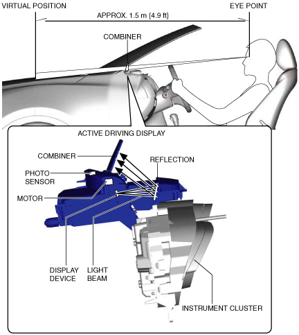
• The active driving display is assembled to the instrument cluster.
• The active driving display consists of a display device which produces the display content and emits the content over a light beam, a reflector which reflects the light beam emitted from the display device, a combiner which reflects the light beam from the reflection and displays the screen, a motor which opens/closes the combiner, and a photo sensor which detects the brightness surrounding the display device.
• The combiner is a processed, clear panel for reflecting the light beam from the display device.
• The combiner opens at the top of the meter hood and displays vehicle information in the forward visual range of the driver. As a result, the time in which the driver's line of vision changes from the view at the front of the vehicle to the view of the vehicle information reflected in the combiner has been shortened.
• By using a concave shaped combiner, the image reflected in the combiner is positioned virtually 1.5 m {4.9 ft} forward of the eye point. As a result, the eye point adjustment time in which the driver's line of vision changes from the view at the front of the vehicle to the view of the vehicle information reflected in the combiner has been reduced.
Operation
1. When the ignition is switched ON (engine on), the combiner is opened based on the following CAN signals (1) .
-
― ROOM fuse status signal from rear body control module (RBCM)
― Combiner target angle signal from connectivity master unit (CMU)
-
Note
-
• When the position memory switch is operated, the active driving display adjusts the angle of the combiner based on the CAN signal (1) from the position memory control module.
2. When the combiner opens, the instrument cluster displays the opening screen (vehicle name) for approx. 2 s. In addition, an active driving display execute signal and combiner current position signal (2) are sent to the CMU.
-
Note
-
• The CMU records the current position of the combiner based on the combiner current position signal from the instrument cluster. When the ignition is switched from OFF to ON (engine running), the target angle signal is sent based on the recorded current position.
• Even if the battery power is disconnected, the combiner current position recorded by the CMU is not cleared.
• If the combiner current position is not recorded, the CMU sends the target angle signal of the initial value.
3. The instrument cluster displays the current vehicle speed based on the vehicle speed signal (3) from the PCM after opening screen is turned off, and displays warning screens based on request signals (3) from related units.
Fail-safe
• The instrument cluster turns off the active driving display images under the following conditions and stops the display at the current position.
-
― Error signal from CMU is received, and CMU malfunction is determined
― Communication with CMU is interrupted
― Motor malfunction for combiner operation is detected