|
1
|
VERIFY FREEZE FRAME DATA (MODE 2)/SNAPSHOT DATA HAS BEEN RECORDED
• Has the FREEZE FRAME DATA (Mode 2)/snapshot data been recorded?
|
Yes
|
Go to the next step.
|
|
No
|
Record the FREEZE FRAME DATA (Mode 2)/snapshot data on the repair order, then go to the next step.
|
|
2
|
VERIFY RELATED SERVICE INFORMATION AVAILABILITY
• Verify related Service Information availability.
• Is any related Service Information available?
|
Yes
|
Perform repair or diagnosis according to the available Service Information.
• If the vehicle is not repaired, go to the next step.
|
|
No
|
Go to the next step.
|
|
3
|
VERIFY RELATED PENDING CODE AND/OR DTC
• Switch the ignition to off, then to ON (engine off).
• Perform the Pending Trouble Code Access Procedure and DTC Reading Procedure.
• Is the PENDING CODE/DTC P1380:00 also present?
|
Yes
|
Go to the applicable PENDING CODE or DTC inspection.
|
|
No
|
Go to the next step.
|
|
4
|
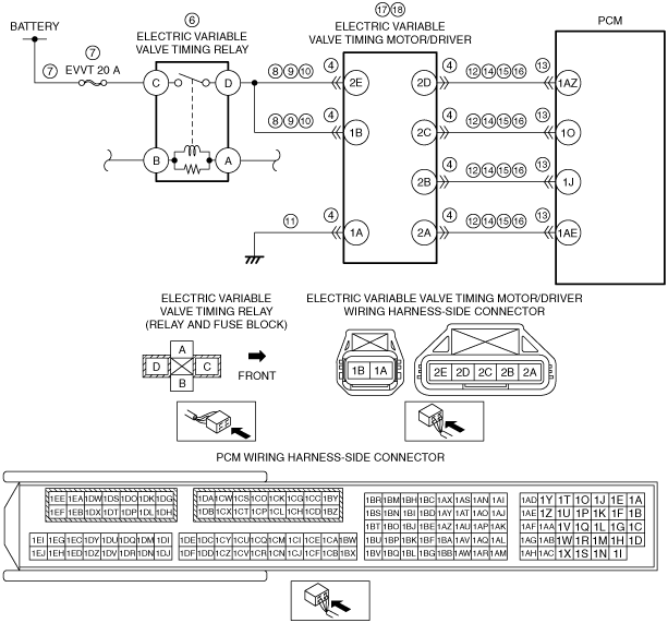
INSPECT ELECTRIC VARIABLE VALVE TIMING MOTOR/DRIVER CONNECTOR CONDITION
• Switch the ignition to off.
• Disconnect the electric variable valve timing motor/driver connector.
• Inspect for poor connection (such as damaged/pulled-out pins, corrosion).
• Is there any malfunction?
|
Yes
|
Repair or replace the connector and/or terminals, then go to Step 19.
|
|
No
|
Go to the next step.
|
|
5
|
DETERMINE IF MALFUNCTION CAUSE IS ELECTRIC VARIABLE VALVE TIMING MOTOR/DRIVER POWER SUPPLY CIRCUIT OR OTHER
• Verify that the electric variable valve timing motor/driver connector is disconnected.
• Start the engine.
• Measure the voltage at the following terminals (wiring harness-side):
-
― Electric variable valve timing motor/driver terminal 2E
― Electric variable valve timing motor/driver terminal 1B
• Is the voltage B+?
|
Yes
|
Go to Step 11.
|
|
No
|
Go to the next step.
|
|
6
|
INSPECT ELECTRIC VARIABLE VALVE TIMING RELAY
• Switch the ignition to off.
• Remove the electric variable valve timing relay.
• Inspect the electric variable valve timing relay.
• Is there any malfunction?
|
Yes
|
Replace the electric variable valve timing relay, then go to Step 19.
|
|
No
|
Go to the next step.
|
|
7
|
INSPECT ELECTRIC VARIABLE VALVE TIMING RELAY POWER SUPPLY CIRCUIT FOR SHORT TO GROUND OR OPEN CIRCUIT
• Electric variable valve timing relay is removed.
• Verify that the electric variable valve timing motor/driver connector is disconnected.
• Measure the voltage at the electric variable valve timing relay terminal C (wiring harness-side).
• Is the voltage B+?
|
Yes
|
Go to the next step.
|
|
No
|
Inspect the EVVT 20 A fuse.
• If the fuse is blown:
-
― Repair or replace the wiring harness for a possible short to ground.
― Replace the fuse.
• If the fuse is deteriorated:
-
― Replace the fuse.
• If the fuse is normal:
-
― Repair or replace the wiring harness for a possible open circuit.
Go to Step 19.
|
|
8
|
INSPECT ELECTRIC VARIABLE VALVE TIMING RELAY CONTROL CIRCUIT FOR SHORT TO GROUND
• Electric variable valve timing relay is removed.
• Verify that the electric variable valve timing motor/driver connector is disconnected.
• Inspect for continuity between electric variable valve timing relay terminal D (wiring harness-side) and body ground.
• Is there continuity?
|
Yes
|
Repair or replace the wiring harness for a possible short to ground, then go to Step 19.
|
|
No
|
Go to the next step.
|
|
9
|
INSPECT ELECTRIC VARIABLE VALVE TIMING RELAY CONTROL CIRCUIT FOR SHORT TO POWER SUPPLY
• Electric variable valve timing relay is removed.
• Verify that the electric variable valve timing motor/driver connector is disconnected.
• Switch the ignition to ON (engine off).
• Measure the voltage at the electric variable valve timing relay terminal D (wiring harness-side).
• Is there any voltage?
|
Yes
|
Repair or replace the wiring harness for a possible short to power supply, then go to Step 19.
|
|
No
|
Go to the next step.
|
|
10
|
INSPECT ELECTRIC VARIABLE VALVE TIMING RELAY CONTROL CIRCUIT FOR OPEN CIRCUIT
• Electric variable valve timing relay is removed.
• Verify that the electric variable valve timing motor/driver connector is disconnected.
• Switch the ignition to off.
• Inspect for continuity between the following terminals (wiring harness-side):
-
― Electric variable valve timing relay terminal D—Electric variable valve timing motor/driver terminal 2E
― Electric variable valve timing relay terminal D—Electric variable valve timing motor/driver terminal 1B
• Is there continuity?
|
Yes
|
Go to Step 19.
|
|
No
|
Repair or replace the wiring harness for a possible open circuit, then go to Step 19.
|
|
11
|
INSPECT ELECTRIC VARIABLE VALVE TIMING MOTOR/DRIVER GROUND CIRCUIT FOR OPEN CIRCUIT
• Verify that the electric variable valve timing motor/driver connector is disconnected.
• Switch the ignition to off.
• Inspect for continuity between electric variable valve timing motor/driver terminal 1A (wiring harness-side) and body ground.
• Is there continuity?
|
Yes
|
Go to the next step.
|
|
No
|
Repair or replace the wiring harness for a possible open circuit, then go to Step 19.
|
|
12
|
INSPECT ELECTRIC VARIABLE VALVE TIMING MOTOR/DRIVER CIRCUIT FOR SHORT TO GROUND
• Verify that the electric variable valve timing motor/driver connector is disconnected.
• Inspect for continuity between the following terminals (wiring harness-side) and body ground:
-
― Electric variable valve timing motor/driver terminal 2D
― Electric variable valve timing motor/driver terminal 2C
― Electric variable valve timing motor/driver terminal 2B
― Electric variable valve timing motor/driver terminal 2A
• Is there continuity?
|
Yes
|
If the short to ground circuit could be detected:
• Repair or replace the wiring harness for a possible short to ground.
If the short to ground circuit could not be detected:
• Replace the PCM (short to ground in the PCM internal circuit).
Go to Step 19.
|
|
No
|
Go to the next step.
|
|
13
|
INSPECT PCM CONNECTOR CONDITION
• Disconnect the PCM connector.
• Inspect for poor connection (such as damaged/pulled-out pins, corrosion).
• Is there any malfunction?
|
Yes
|
Repair or replace the connector and/or terminals, then go to Step 19.
|
|
No
|
Go to the next step.
|
|
14
|
INSPECT ELECTRIC VARIABLE VALVE TIMING MOTOR/DRIVER CIRCUIT FOR SHORT TO POWER SUPPLY
• Verify that the electric variable valve timing motor/driver and PCM connectors are disconnected.
• Switch the ignition to ON (engine off).
• Measure the voltage at the following terminals (wiring harness-side):
-
― Electric variable valve timing motor/driver terminal 2D
― Electric variable valve timing motor/driver terminal 2C
― Electric variable valve timing motor/driver terminal 2B
― Electric variable valve timing motor/driver terminal 2A
• Is there any voltage?
|
Yes
|
Repair or replace the wiring harness for a possible short to power supply, then go to Step 19.
|
|
No
|
Go to the next step.
|
|
15
|
INSPECT ELECTRIC VARIABLE VALVE TIMING MOTOR/DRIVER CIRCUITS FOR SHORT TO EACH OTHER
• Verify that the electric variable valve timing motor/driver and PCM connectors are disconnected.
• Switch the ignition to off.
• Inspect for continuity electric variable valve timing motor/driver terminals 2D, 2C, 2B and 2A (wiring harness-side).
• Is there continuity?
|
Yes
|
Repair or replace the wiring harness for a possible short to each other, then go to Step 19.
|
|
No
|
Go to the next step.
|
|
16
|
INSPECT ELECTRIC VARIABLE VALVE TIMING MOTOR/DRIVER CIRCUIT FOR OPEN CIRCUIT
• Verify that the electric variable valve timing motor/driver and PCM connectors are disconnected.
• Inspect for continuity between the following terminals (wiring harness-side):
-
― Electric variable valve timing motor/driver terminal 2D—PCM terminal 1AZ
― Electric variable valve timing motor/driver terminal 2C—PCM terminal 1O
― Electric variable valve timing motor/driver terminal 2B—PCM terminal 1J
― Electric variable valve timing motor/driver terminal 2A—PCM terminal 1AE
• Is there continuity?
|
Yes
|
Go to the next step.
|
|
No
|
Repair or replace the wiring harness for a possible open circuit, then go to Step 19.
|
|
17
|
INSPECT ELECTRIC VARIABLE VALVE TIMING DRIVER
• Inspect the electric variable valve timing driver.
• Is there any malfunction?
|
Yes
|
Replace the electric variable valve timing motor/driver, then go to Step 19.
|
|
No
|
Go to the next step.
|
|
18
|
INSPECT ELECTRIC VARIABLE VALVE TIMING MOTOR
• Inspect the electric variable valve timing motor.
• Is there any malfunction?
|
Yes
|
Replace the electric variable valve timing motor/driver, then go to the next step.
|
|
No
|
Go to the next step.
|
|
19
|
VERIFY DTC TROUBLESHOOTING COMPLETED
• Make sure to reconnect all disconnected connectors.
• Clear the DTC from the PCM memory using the M-MDS.
• Perform the KOER self test.
• Is the same DTC present?
|
Yes
|
Repeat the inspection from Step 1.
• If the malfunction recurs, replace the PCM.
Go to the next step.
|
|
No
|
Go to the next step.
|
|
20
|
VERIFY AFTER REPAIR PROCEDURE
• Perform the “AFTER REPAIR PROCEDURE”.
• Are any DTCs present?
|
Yes
|
Go to the applicable DTC inspection.
|
|
No
|
DTC troubleshooting completed.
|