ELECTRIC VARIABLE VALVE TIMING MOTOR/DRIVER REMOVAL/INSTALLATION [SKYACTIV-G 2.0]


id0110h2808100

Warning
•   A hot engine can cause severe burns. Turn off the engine and wait until it is cool before servicing.
Caution
•  Applying excessive force (force of 100 N {10.2 kgf, 22.5 lbf} or more) to the electric variable valve timing motor/driver may cause a malfunction. When servicing, be careful not to apply excessive force to the electric variable valve timing motor/driver using other parts or tools.
•  Do not disassemble the electric variable valve timing motor/driver because it is a precision unit.

1.  Remove the battery cover. (See BATTERY REMOVAL/INSTALLATION [SKYACTIV-G 2.0].)

2.  Disconnect the negative battery cable. (See BATTERY REMOVAL/INSTALLATION [SKYACTIV-G 2.0].)

3.  Remove the plug hole plate. (See PLUG HOLE PLATE REMOVAL/INSTALLATION [SKYACTIV-G 2.0].)

4.  Remove the coolant reserve tank with the hose still connected and set it out of the way. (See COOLANT RESERVE TANK REMOVAL/INSTALLATION [SKYACTIV-G 2.0].)

5.  Remove in the order indicated in the table.

6.  Install in the reverse order of removal.

am3uuw00008903

1
No. 3 engine mount
2
Electric variable valve timing motor/driver connector
3
Electric variable valve timing motor/driver
4
O-ring


No.3 Engine Mount Removal Note

1.  Remove the cooler hose bracket bolt and set the cooler hose aside.

am3uuw00008904

2.  Remove the aerodynamic under cover No.2. (See AERODYNAMIC UNDER COVER NO.2 REMOVAL/INSTALLATION.)

Caution
•  To prevent deformation of the oil pan, support the engine using the following methods.
―  When using an engine lifter, insert rubber of appropriate size (approx. 20 mm {0.79 in} thickness) between the engine lifter and the oil pan to support the oil pan.
―  When using a garage jack, place rubber of appropriate size (approx. 20 mm {0.79 in} thickness) on a batten which is large enough to cover the oil pan to support the oil pan.

3.  Before removing the No.3 engine mount, support the engine (oil pan) using a commercially available engine lifter or garage jack.

am3uuw00008905

4.  Remove the No. 3 engine mount.


Electric Variable Valve Timing Motor/Driver Installation Note

1.  Install a new O-ring to the O-ring installation groove of the engine front cover.

Caution
•  To prevent damage to the electric variable valve timing motor/driver, do not apply excessive force (force of 100 N {10.2 kgf, 22.5 lbf} or more) to the shaded areas shown in the figure.
am3uuw00008906

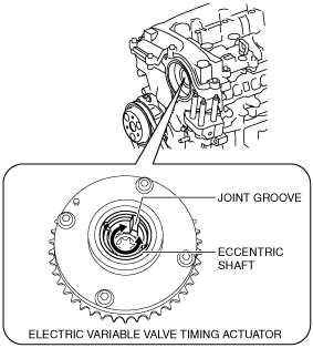
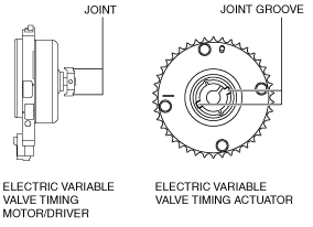
2.  Install the electric variable valve timing motor/driver using the following procedures.

Note
•  The eccentric shaft on the electric variable valve timing actuator side can be rotated to the left and right.
am3uuw00009046
•  The electric variable valve timing motor/driver can be assembled with the joint groove of the eccentric shaft in any position, and it will not lead to vehicle damage or performance reduction.
(1)  Before installation, rotate the joint of the end of the electric variable valve timing motor so that it is aligned to the joint groove on the electric variable valve timing actuator side.
am3uuw00009047
(2)  Engage the joint on the end of the electric variable valve timing motor with the joint groove on the electric variable valve timing actuator side.
(3)  Attach the seal surface.
(4)  Tighten the electric variable valve timing motor/driver installation bolts.
Tightening torque
20—26 N·m {2.1—2.6 kgf·m, 15—19 ft·lbf}


No.3 Engine Mount Installation Note

Note
•  If the No.3 engine mount nut is loosened, tighten the stud bolts for the No.3 engine mount bracket because they may be loosened.

1.  Tighten the No.3 engine mount stud bolts.

am3uuw00009028

Tightening torque
7—13 N·m {72—132 kgf·cm, 62—115 in·lbf}

2.  Install the No.3 engine mount and temporarily tighten the bolts and nuts.

3.  Tighten the No.3 engine mount installation bolts and nuts in the order as shown in the figure.

am3uuw00008910

No.
Tightening torque
1
75—104 N·m {7.7—10 kgf·m, 56—76 ft·lbf}
2
71—93 N·m {7.3—9.4 kgf·m, 53—68 ft·lbf}

4.  Remove the engine lifter or garage jack.

5.  Install the aerodynamic under cover No.2. (See AERODYNAMIC UNDER COVER NO.2 REMOVAL/INSTALLATION.)

6.  Install the cooler hose bracket bolt.