|
am3zzw00012016
INTAKE-AIR SYSTEM REMOVAL/INSTALLATION [MZR 2.0, MZR 2.5]
id0113d2801900
1. Complete the “BEFORE SERVICE PRECAUTION”. (See BEFORE SERVICE PRECAUTION [MZR 2.0, MZR 2.5].)
2. Remove the battery cover. (See BATTERY REMOVAL/INSTALLATION [MZR 2.0, MZR 2.5].)
3. Disconnect the negative battery cable. (See BATTERY REMOVAL/INSTALLATION [MZR 2.0, MZR 2.5].)
4. Remove the plug hole plate. (See PLUG HOLE PLATE REMOVAL/INSTALLATION [MZR 2.0, MZR 2.5].)
5. Disconnect the wiring harness.
6. Remove in the order indicated in the table.
7. Install in the reverse order of removal.
8. Complete the “AFTER SERVICE PRECAUTION”. (See AFTER SERVICE PRECAUTION [MZR 2.0, MZR 2.5].)
Step 1
am3zzw00012016
|
|
1
|
MAF/IAT sensor
|
|
2
|
Ventilation hose
|
|
3
|
Air cleaner cover
|
|
4
|
Resonance chamber
|
|
5
|
Air hose
|
|
6
|
Air cleaner element
|
|
7
|
Air cleaner case
|
|
8
|
Fresh-air duct (No.1)
|
|
9
|
Fresh-air duct (No.2)
|
|
10
|
Fresh-air duct (No.3)
|
Step 2
am3zzw00012017
|
|
1
|
Water hose
(SeeWater Hose Removal Note.)
|
|
2
|
Throttle body
|
|
3
|
Vacuum hose
|
|
4
|
Variable intake air solenoid valve
|
|
5
|
Vacuum hose
|
|
6
|
Variable tumble solenoid valve
|
|
7
|
Vacuum hose
|
|
8
|
Quick release connector
|
|
9
|
Vacuum cap (MZR 2.5)
|
|
10
|
Intake manifold
(See Intake Manifold Removal Note.)
|
Air Cleaner Cover Removal Note
1. Remove the air cleaner cover and resonance chamber and air hose a as single unit.
2. Remove the air cleaner cover.
Fresh-Air Duct (No.1) Removal Note
1. Remove the fresh-air duct (No.1) and fresh-air duct (No.2) a as single unit.
2. Remove the fresh-air duct (No.1).
Water Hose Removal Note
1. Drain the engine coolant. (See ENGINE COOLANT REPLACEMENT [MZR 2.0, MZR 2.5].)
2. Disconnect the water hose.
Intake Manifold Removal Note
1. Remove the aerodynamic under cover No.2. (See AERODYNAMIC UNDER COVER NO.2 REMOVAL/INSTALLATION.)
2. Remove all clips for securing wiring harnesses from the intake manifold.
3. Disconnect the vacuum hoses connecting the intake manifold.
4. Remove the fuel distributor and fuel injector a as single unit. (See FUEL INJECTOR REMOVAL/INSTALLATION [MZR 2.0, MZR 2.5].)
5. Remove the intake manifold.
Throttle Body Installation Note
1. Tighten the installation bolts in the order shown in the figure.
am6xuw00001432
|
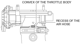
Air Hose Installation Note
1. Adjust the convex of the throttle body to the recess of the air hose.
am3uuw00002488
|