SUPPLY PUMP REMOVAL/INSTALLATION [MZ-CD 1.6]
id011420805700
-
Warning
-
• Do not smoke or carry lighted tobacco or open flame of any type when working on or near any fuel related components. Highly flammable mixtures are always present and may ignite. Failure to follow these instructions may result in personal injury.
• This procedure involves fuel handling. Be prepared for fuel spillage at all times and always observe fuel handling precautions. Failure to follow these instructions may result in personal injury.
• Wait at least one minute after the engine stops before commencing any repair to the fuel injection system. Failure to follow this instruction may result in personal injury.
-
Caution
-
• Diesel fuel injection equipment is manufactured to very precise tolerances and fine clearances. It is therefore essential that absolute cleanliness is observed when working with these components. Always install blanking plugs to any open orifices or lines.
• Do not disassemble fuel injectors or clean the nozzles, even with an ultrasonic cleaner. Always install new fuel injectors when required.
• Always carry out the cleaning process before carrying out any repairs to the fuel injection system components to prevent foreign matter ingress to the components.
-
Note
-
1. Remove the battery cover. (See BATTERY REMOVAL/INSTALLATION [MZ-CD 1.6].)
2. Disconnect the negative battery cable. (See BATTERY REMOVAL/INSTALLATION [MZ-CD 1.6].)
3. Remove the fuel metering valve. (See FUEL METERING VALVE REMOVAL/INSTALLATION [MZ-CD 1.6].)
4. Remove the following parts:
- (1) Engine cover (See ENGINE COVER REMOVAL/INSTALLATION [MZ-CD 1.6].)
- (2) Drive belt (See DRIVE BELT REMOVAL/INSTALLATION [MZ-CD 1.6].)
- (3) Coolant reserve tank with the hoses and pipes still connected (See COOLANT RESERVE TANK REMOVAL/INSTALLATION [MZ-CD 1.6].)
5. Set the cooler hose (LO) out of the way. (See REFRIGERANT LINE REMOVAL/INSTALLATION.)
6. Remove the timing belt. (See TIMING BELT REMOVAL/INSTALLATION [MZ-CD 1.6].)
7. Remove and dispose of the injection pipe (supply pump side). (See COMMON RAIL REMOVAL/INSTALLATION [MZ-CD 1.6].)
8. The position shown in figure is protected with the tape.
9. Remove the nut using the SST as shown in the figure.
10. Remove the bolt as shown in the figure.
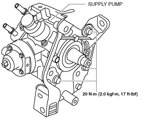
11. Remove the supply pump and supply pump bracket No.1 and supply pump pulley as single unit.
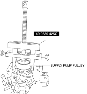
12. Install the SST as shown in the figure.
13. Remove the supply pump pulley.
14. Remove the supply pump.
15. Remove the supply pump bracket No.2.
16. Install in the reverse order of removal.