 |
am3zzw00010973
REFRIGERANT LINE REMOVAL/INSTALLATION
id071100803000
SKYACTIV-G 2.0
1. Disconnect the negative battery cable. (See BATTERY REMOVAL/INSTALLATION [SKYACTIV-G 2.0].)
2. Discharge the refrigerant. (See REFRIGERANT CHARGING.)
3. Set the coolant reserve tank out of the way. (See COOLANT RESERVE TANK REMOVAL/INSTALLATION [SKYACTIV-G 2.0].)
4. Disconnect the refrigerant pressure sensor connector.
5. Remove in the order indicated in the table. Do not allow compressor oil to spill.
6. Install in the reverse order of removal.
7. Perform the refrigerant system performance test. (See REFRIGERANT SYSTEM PERFORMANCE TEST.)
am3zzw00010973
|
|
1
|
Cooler hose (HI)
|
|
2
|
Cooler hose (LO)
|
|
3
|
Cooler pipe
|
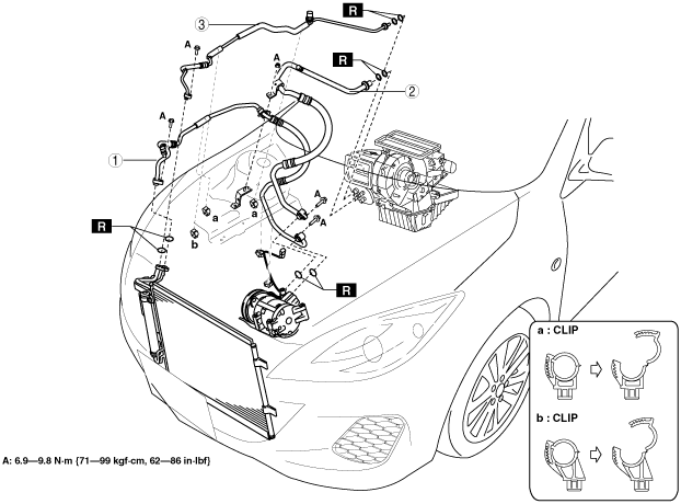
MZR 2.5
1. Disconnect the negative battery cable. (See BATTERY REMOVAL/INSTALLATION [MZR 2.0, MZR 2.5].)
2. Discharge the refrigerant. (See REFRIGERANT CHARGING.)
3. Set the coolant reserve tank out of the way. (See COOLANT RESERVE TANK REMOVAL/INSTALLATION [MZR 2.0, MZR 2.5].)
4. Disconnect the refrigerant pressure sensor connector.
5. Remove in the order indicated in the table. Do not allow compressor oil to spill.
6. Install in the reverse order of removal.
7. Perform the refrigerant system performance test. (See REFRIGERANT SYSTEM PERFORMANCE TEST.)
am3zzw00010974
|
|
1
|
Cooler hose (HI)
|
|
2
|
Cooler hose (LO)
|
|
3
|
Cooler pipe
|
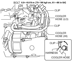
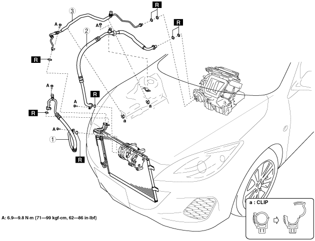
MZR 2.0, MZR 2.0 DISI i-stop
1. Disconnect the negative battery cable. (See BATTERY REMOVAL/INSTALLATION [MZR 2.0, MZR 2.5].) (See BATTERY REMOVAL/INSTALLATION [MZR 2.0 DISI i-stop].)
2. Discharge the refrigerant. (See REFRIGERANT CHARGING.)
3. Disconnect the refrigerant pressure sensor connector.
4. Remove the clip.
am3zzw00010975
|
5. Remove the bolt.
6. Remove the cooler hose (HI) and cooler hose (LO).
7. Remove the P/S fluid reserve tank.
8. Set the coolant reserve tank out of the way. (See COOLANT RESERVE TANK REMOVAL/INSTALLATION [MZR 2.0, MZR 2.5].) (See COOLANT RESERVE TANK REMOVAL/INSTALLATION [MZR 2.0 DISI i-stop].)
9. Remove the front splash shield.
10. Remove the cooler pipe.
11. Install in the reverse order of removal.
12. Perform the refrigerant system performance test. (See REFRIGERANT SYSTEM PERFORMANCE TEST.)
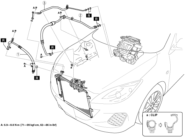
am3zzw00010976
|
|
1
|
Cooler hose (HI)
|
|
2
|
Cooler hose (LO)
|
|
3
|
Cooler pipe
|
MZR 1.5, MZR 1.6
1. Disconnect the negative battery cable. (See BATTERY REMOVAL/INSTALLATION [MZR 1.5, MZR 1.6].)
2. Discharge the refrigerant. (See REFRIGERANT CHARGING.)
3. Set the coolant reserve tank out of the way. (See COOLANT RESERVE TANK REMOVAL/INSTALLATION [MZR 1.5, MZR 1.6].)
4. Disconnect the refrigerant pressure switch connector.
5. Remove in the order indicated in the table. Do not allow compressor oil to spill.
6. Install in the reverse order of removal.
7. Perform the refrigerant system performance test. (See REFRIGERANT SYSTEM PERFORMANCE TEST.)
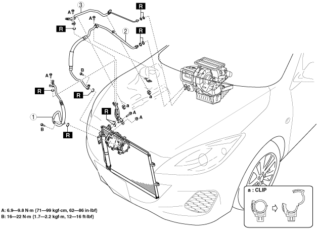
am3zzw00010977
|
|
1
|
Cooler hose (HI)
|
|
2
|
Cooler hose (LO)
|
|
3
|
Cooler pipe
|
MZ-CD 1.6
1. Disconnect the negative battery cable. (See BATTERY REMOVAL/INSTALLATION [MZ-CD 1.6].)
2. Discharge the refrigerant. (See REFRIGERANT CHARGING.)
3. Set the coolant reserve tank out of the way.
4. Disconnect the refrigerant pressure switch connector. (See REFRIGERANT PRESSURE SENSOR REMOVAL/INSTALLATION [FULL-AUTO AIR CONDITIONER].) (See REFRIGERANT PRESSURE SENSOR REMOVAL/INSTALLATION [MANUAL AIR CONDITIONER].)
5. Remove in the order indicated in the table. Do not allow compressor oil to spill.
6. Install in the reverse order of removal.
7. Perform the refrigerant system performance test. (See REFRIGERANT SYSTEM PERFORMANCE TEST.)
am3zzw00010978
|
|
1
|
Cooler hose (HI)
|
|
2
|
Cooler hose (LO)
|
|
3
|
Cooler pipe
|
MZR-CD 2.2
1. Disconnect the negative battery cable. (See BATTERY REMOVAL/INSTALLATION [MZR-CD 2.2].)
2. Discharge the refrigerant. (See REFRIGERANT CHARGING.)
3. Set the coolant reserve tank out of the way. (See COOLANT RESERVE TANK REMOVAL/INSTALLATION [MZR-CD 2.2].)
4. Disconnect the refrigerant pressure switch connector.
5. Remove in the order indicated in the table. Do not allow compressor oil to spill.
6. Install in the reverse order of removal.
7. Perform the refrigerant system performance test. (See REFRIGERANT SYSTEM PERFORMANCE TEST.)
am3zzw00010979
|
|
1
|
Cooler hose (HI)
|
|
2
|
Cooler pipe No.2
|
|
3
|
Cooler hose (LO)
|
|
4
|
Cooler pipe No.1
|
MZR 2.3 DISI Turbo
1. Disconnect the negative battery cable. (See BATTERY REMOVAL/INSTALLATION [MZR 2.3 DISI Turbo].)
2. Discharge the refrigerant. (See REFRIGERANT CHARGING.)
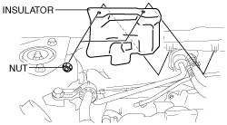
3. Remove the charge air cooler cover. (See INTAKE-AIR SYSTEM REMOVAL/INSTALLATION [MZR 2.3 DISI Turbo].)
4. Remove the insulator.
am3zzw00011931
|
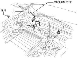
5. Remove the nut and disconnect the vacuum pipe then set the vacuum pipe out of the way. (R.H.D.)
am3zzw00008577
|
6. Set the coolant reserve tank out of the way. (See COOLANT RESERVE TANK REMOVAL/INSTALLATION [MZR 2.3 DISI Turbo].)
7. Disconnect the refrigerant pressure sensor connector.
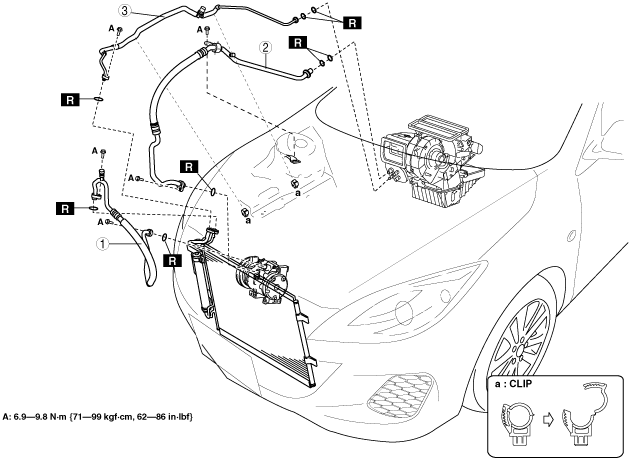
8. Remove in the order indicated in the table. Do not allow compressor oil to spill.
9. Install in the reverse order of removal.
10. Perform the refrigerant system performance test. (See REFRIGERANT SYSTEM PERFORMANCE TEST.)
am3zzw00010980
|
|
1
|
Cooler hose (HI)
|
|
2
|
Cooler hose (LO)
|
|
3
|
Cooler pipe
|
Refrigerant Line Removal Note
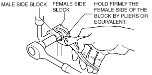
Block joint type
1. Disconnect the block joint type pipes by grasping female side of the block with pliers or similar tool and holding firmly, then remove the connection bolt or nut.
am3zzw00010981
|
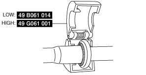
Spring-lock coupling type
1. Set the SST.
am3zzw00010982
|
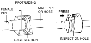
2. While looking through the inspection hole of the SST, insert the protruding part of the SST until it makes contact with the cage section.
am3zzw00010983
|
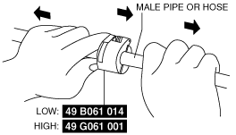
3. Use the SST to disconnect the male pipe or hose from the female by pulling the male pipe or hose.
am3zzw00010984
|
Refrigerant Line Installation Note
1. Apply compressor oil to the O-rings and connect the joints.
2. Tighten the joints.
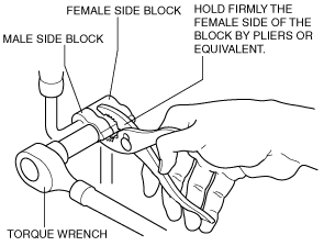
Block joint type
1. Tighten the bolt of joint by hand.
2. Connect the block joint type pipes by grasping the female side of the block with pliers or similar tool and holding firmly, then tighten the connection bolt or nut with a torque wrench.
am3zzw00010985
|
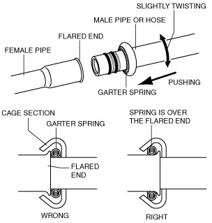
Spring-lock coupling type
1. Connect the male pipe or hose by twisting it onto female pipe until the garter spring at the male pipe or hose is over the flared end of female pipe.
am3zzw00010986
|
Cooler Hose (LO) Installation Note
1. After replacing the cooler hose (LO), add compressor oil to the refrigeration cycle.
Cooler Pipe Installation Note
1. After replacing the cooler pipe, add compressor oil to the refrigeration cycle.