 |
am3uuw00008405
JOINT SHAFT REMOVAL/INSTALLATION [SKYACTIV-G 2.0]
id0313008009x4
1. Remove the aerodynamic under cover No.2 and splash shield as a unit. (See AERODYNAMIC UNDER COVER NO.2 REMOVAL/INSTALLATION.) (See SPLASH SHIELD REMOVAL/INSTALLATION.)
2. Drain the ATF. (See AUTOMATIC TRANSAXLE FLUID (ATF) REPLACEMENT [FW6A-EL].)
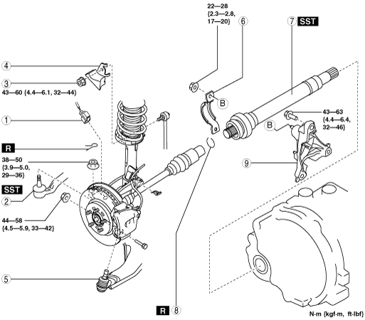
3. Remove in the order indicated in the table.
4. Install in the reverse order of removal.
am3uuw00008405
|
|
1
|
ABS wheel-speed sensor connector
|
|
2
|
Tie-rod end ball joint
|
|
3
|
Stabilizer control link upper nut
|
|
4
|
Dynamic damper
|
|
5
|
Front lower arm ball joint
|
|
6
|
Joint shaft bracket No.2
|
|
7
|
Joint shaft
(See Joint Shaft Removal Note.)
|
|
8
|
Joint shaft clip
|
|
9
|
Joint shaft bracket No.1
|
Joint Shaft Removal Note
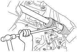
1. Disconnect the drive shaft (RH) from the joint shaft by tapping the transaxle side outer ring with a brass bar and hammer.
am3zzw00002051
|
2. Remove the joint shaft bracket No.2 from the joint shaft bracket No.1.
3. Remove the joint shaft.
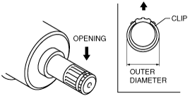
Joint Shaft Clip Installation Note
1. Install a new joint shaft clip to the clip groove at the end of the joint shaft with the clip opening facing upward and the clip width within the specification.
2. After installation, measure the outer diameter.
am3uuw00006183
|
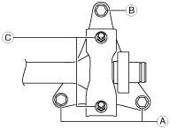
Joint Shaft Bracket, Joint shaft Installation Note
1. Tighten the joint shaft bracket No.1 stud bolts.
am3zzw00012332
|
2. Temporarily tighten the bolts A and B.
am3uuw00008407
|
3. Tighten the bolts A, then tighten the bolt B to the specified torque.
4. Install the joint shaft into the transaxle.
5. Temporarily tighten the nuts C, then tighten the nuts C to the specified torque.
Front Lower Arm Ball Joint Installation Note