 |
am3zzw00005773
POWER BRAKE UNIT REMOVAL/INSTALLATION (R.H.D.) [MZR-CD 2.2]
id0411008038g1
1. Remove the engine cover. (See ENGINE COVER REMOVAL/INSTALLATION [MZR-CD 2.2].)
2. Remove the windshield wiper arm and blade. (See WINDSHIELD WIPER ARM AND BLADE REMOVAL/INSTALLATION.)
3. Remove the cowl grille. (See COWL GRILLE REMOVAL/INSTALLATION.)
4. Remove the cowl panel. (See COWL PANEL REMOVAL/INSTALLATION.)
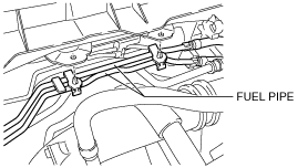
5. Remove the fuel pipes.
am3zzw00005773
|
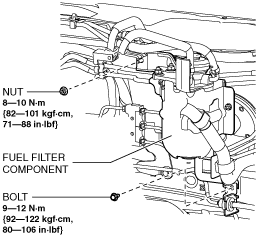
6. Remove the fuel filter installation nut and bolt.
am3zzw00005774
|
7. Remove the fuel filter component from the vehicle.
8. Set the fuel filter component out of the way.
9. Remove the master cylinder. (See MASTER CYLINDER REMOVAL/INSTALLATION [MZR 1.5, MZR 1.6, MZR 2.0, MZR 2.5, MZ-CD 1.6, MZR-CD 2.2].)
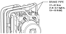
10. Disconnect the brake pipes.
am3zzw00005775
|
11. Detach the brake pipes from the brake pipe bracket.
am3zzw00006123
|
12. Remove the brake pipes from the vehicle.
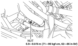
13. Remove the cooler hose (LO) installation nut.
am3zzw00006124
|
14. Remove the cooler hose (LO) from the clip.
am3zzw00006125
|
15. Move the cooler hose (LO) in the direction of the arrow.
16. Disconnect the steering shaft from the steering gear and linkage. (See STEERING WHEEL AND COLUMN REMOVAL/INSTALLATION [WITHOUT ADVANCED KEYLESS ENTRY AND PUSH BUTTON START SYSTEM].) (See STEERING WHEEL AND COLUMN REMOVAL/INSTALLATION [WITH ADVANCED KEYLESS ENTRY AND PUSH BUTTON START SYSTEM].)
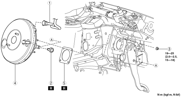
17. Remove in the order indicated in the table.
18. Remove the brake switch. (See BRAKE PEDAL REMOVAL/INSTALLATION [R.H.D.].)
19. Install in the reverse order of removal.
20. After installation, inspect the brake pedal. (See BRAKE PEDAL INSPECTION.)
am3zzw00007045
|
|
1
|
Vacuum hose
(See Vacuum Hose Removal Note.)
|
|
2
|
Joint pin
|
|
3
|
Nut
|
|
4
|
Power brake unit
|
|
5
|
Gasket
|
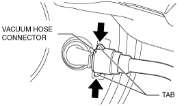
Vacuum Hose Removal Note
1. Disconnect the vacuum hose connector from the power brake unit while pressing the tabs of the vacuum hose connector.
am3zzw00006074
|
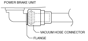
Vacuum Hose Installation Note
1. Insert the vacuum hose connector to the power brake unit.
2. Verify that the vacuum hose is inserted so that the connector contacts the power brake unit flange.
am3uuw00001800
|