DTC P0819:00 [DJVA-EL]


id0502l1822400

DTC P0819:00

M range switch/up switch/down switch circuit malfunction (open circuit/short circuit)

DETECTION CONDITION
•  Condition: TCM communication normal
•  Status: Continuously detects that the M range switch is ON for a 2.5 s period while the selector lever is in the P, R or N position.
Continuously detects that the up switch is ON or the down switch is ON while the M range switch is ON.
•  Period: Confirmed 1 time.
Diagnostic support note
•  The AT warning light illuminates if the TCM detects the above malfunction condition during the first drive cycle.
•  PENDING CODE is not available.
•  The DTC is stored in the TCM memory.
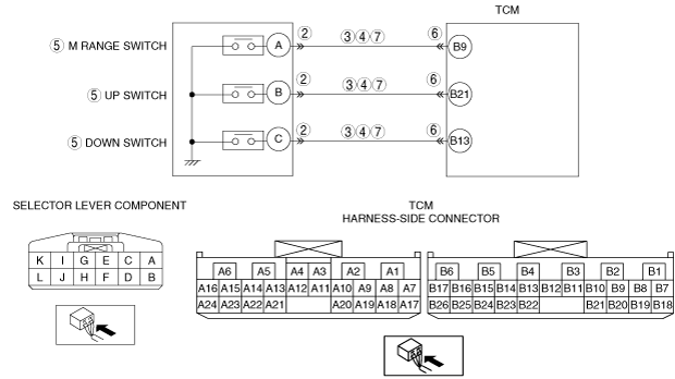
POSSIBLE CAUSE
•  Selector lever component connector or terminal malfunction
•  Short to GND in wiring harness for selector lever component terminal C and TCM terminal B13
•  Short to GND in wiring harness for selector lever component terminal B and TCM terminal B21
•  Short to GND in wiring harness for selector lever component terminal A and TCM terminal B9
•  Short to power supply in wiring harness for selector lever component terminal C and TCM terminal B13
•  Short to power supply in wiring harness for selector lever component terminal B and TCM terminal B21
•  Short to power supply in wiring harness for selector lever component terminal A and TCM terminal B9
•  M range switch malfunction
•  Up switch malfunction
•  Down switch malfunction
•  TCM connector or terminal malfunction
•  Open circuit in wiring harness for selector lever component terminal C and TCM terminal B13
•  Open circuit in wiring harness for selector lever component terminal B and TCM terminal B21
•  Open circuit in wiring harness for selector lever component terminal A and TCM terminal B9
•  TCM malfunction

Diagnostic procedure

STEP

INSPECTION

ACTION

1
VERIFY RELATED REPAIR INFORMATION AVAILABILITY
•  Verify related service information availability.
•  Is any related repair information available?
Yes
Perform repair or diagnosis according to the available repair information.
•  If the vehicle is not repaired, go to the next step.
No
Go to the next step.
2
INSPECT SELECTOR LEVER COMPONENT CONNECTOR FOR POOR CONNECTION
•  Switch the ignition to OFF.
•  Disconnect the selector lever component connector.
•  Inspect for poor connection (such as damaged/pulled-out pins, corrosion)
•  Is there any malfunction?
Yes
Repair or replace the terminal, then go to Step 8.
No
Go to the next step.
3
INSPECT M RANGE SWITCH, UP SWITCH OR DOWN SWITCH CIRCUIT FOR SHORT TO GND
•  Switch the ignition to OFF.
•  Inspect for continuity between the following circuits:
―  Selector lever component terminal C (wiring harness-side) and body GND
―  Selector lever component terminal B (wiring harness-side) and body GND
―  Selector lever component terminal A (wiring harness-side) and body GND
•  Is the voltage B+?
Yes
Repair or replace the wiring harness for a possible short to power supply, then go to Step 8.
No
Go to the next step.
4
INSPECT M RANGE SWITCH, UP SWITCH AND DOWN SWITCH CIRCUIT FOR SHORT TO POWER SUPPLY
•  Switch the ignition to ON. (engine off).
•  Measure the voltage between the following circuits:
―  Selector lever component terminal C (wiring harness-side) and body GND
―  Selector lever component terminal B (wiring harness-side) and body GND
―  Selector lever component terminal A (wiring harness-side) and body GND
•  Is there continuity?
Yes
Repair or replace the wiring harness for a possible short to GND, then go to Step 8.
No
Go to the next step.
5
INSPECT M RANGE SWITCH, UP SWITCH AND DOWN SWITCH
•  Inspect the selector lever component
•  Is there any malfunction?
Yes
Replace the selector lever component, then go to Step 8.
No
Go to the next step.
6
INSPECT TCM CONNECTOR FOR POOR CONNECTION
•  Switch the ignition to OFF.
•  Disconnect the TCM connector.
•  Inspect for poor connection (such as damaged/pulled-out pins, corrosion)
•  Is there any malfunction?
Yes
Repair or replace the terminal, then go to Step 8.
No
Go to the next step.
7
INSPECT M RANGE SWITCH, UP SWITCH AND DOWN SWITCH CIRCUIT FOR OPEN CIRCUIT
•  Switch the ignition to OFF.
•  Inspect for continuity between the following circuits:
―  Selector lever component terminal C (wiring harness-side) and TCM terminal B13 (wiring harness-side)
―  Selector lever component terminal B (wiring harness-side) and TCM terminal B21 (wiring harness-side)
―  Selector lever component terminal A (wiring harness-side) and TCM terminal B9 (wiring harness-side)
•  Is there continuity?
Yes
Repair or replace the wiring harness for a possible open circuit, then go to the next step.
No
Go to the next step.
8
VERIFY DTC TROUBLESHOOTING COMPLETED
•  Make sure to reconnect all the disconnected connectors.
•  Clear the DTC using the M-MDS.
•  Perform the following procedure to ensure that the DTC has been resolved:
1.  Start the engine.
•  Is the same DTC present?
Yes
Perform the following procedure, then go to next step.
1.  Replace the TCM.
2.  Perform TCM learning.
No
Go to the next step.
9
VERIFY NO DTCs ARE PRESENT
•  Perform the “Reading DTCs Procedure”.
•  Are any DTCs present?
Yes
Go to the applicable DTC inspection.
No
DTC troubleshooting completed.