|
am3zzw00008404
CLUTCH UNIT REMOVAL/INSTALLATION [A26M-R (MZR 2.3 DISI Turbo)]
id0510008003c4
1. Remove the battery cover. (See BATTERY RECHARGING [MZR 2.3 DISI Turbo].)
2. Disconnect the negative battery cable. (See BATTERY RECHARGING [MZR 2.3 DISI Turbo].)
3. Drain the engine coolant. (See ENGINE COOLANT REPLACEMENT [MZR-CD 2.2].)
4. Remove the PCM cover No.1. (See PCM REMOVAL/INSTALLATION [MZR 2.3 DISI Turbo].)
5. Disconnect the PCM connector. (See PCM REMOVAL/INSTALLATION [MZR 2.3 DISI Turbo].)
6. Remove the following parts:
7. Remove the starter. (See STARTER REMOVAL/INSTALLATION [MZR 2.3 DISI Turbo].)
8. Remove the front auto leveling sensor. (See AUTO LEVELING SENSOR REMOVAL/INSTALLATION.)
9. Drain the transaxle oil into a suitable container. (See TRANSAXLE OIL REPLACEMENT [A26M-R].)
10. Remove the manual transaxle. (See MANUAL TRANSAXLE REMOVAL/INSTALLATION [A26M-R (MZR 2.3 DISI Turbo)].)
11. Remove in the order indicated in the table.
12. Install in the reverse order of removal.
13. Add the specified amount of specified transaxle oil. (See TRANSAXLE OIL REPLACEMENT [A26M-R].)
14. Warm up the engine and transaxle, inspect for oil leakage, and inspect the transaxle operation.
am3zzw00008404
|
|
1
|
Boot
|
|
2
|
Clutch release collar
|
|
3
|
Clutch release fork
|
|
4
|
Clutch cover
|
|
5
|
Clutch disc
|
|
6
|
Pilot bearing
(See Pilot Bearing Removal Note.)
|
|
7
|
Flywheel
(See Flywheel Removal Note.)
(See Flywheel Installation Note.)
|
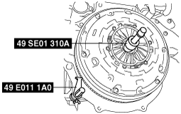
Clutch Cover and Disc Removal Note
1. Install the SSTs.
am3zzw00008461
|
2. Loosen each bolt one turn at a time in a crisscross pattern until spring tension is released.
3. Remove the clutch cover and disc.
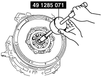
Pilot Bearing Removal Note
1. Use the SST to remove the pilot bearing.
am3zzw00008738
|
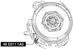
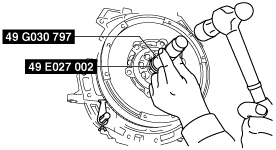
Flywheel Removal Note
1. Hold the flywheel using the SST.
am3zzw00008739
|
2. Remove the bolts evenly and gradually in a crisscross pattern.
3. Remove the flywheel.
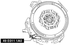
Flywheel Installation Note
1. Clean the crankshaft thread holes.
2. Install the flywheel to the crankshaft.
3. Hand-tighten the new flywheel lock bolts.
4. Install the SST to the flywheel.
am3zzw00008740
|
5. Gradually tighten the flywheel lock bolts in a crisscross pattern.
Pilot Bearing Installation Note
1. Use the SSTs to install the pilot bearing.
am3zzw00008741
|
2. As shown in the figure, press-fit the pilot bearing to the position which is 4.0—5.0 mm {0.16—0.19 in} from the crankshaft end.
am3zzw00007712
|
Clutch Disc Installation Note
1. Clean the splines of the clutch disc and the main drive gear with a brush.
2. Spread a thin layer of clutch grease on the splines.
3. Hold the clutch disc position using the SST.
am3zzw00008466
|
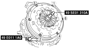
Clutch Cover Installation Note
1. Install the SSTs.
am3zzw00008467
|
2. Tighten the bolts in Min. 2 stages.
3. Tighten partially with a crisscross pattern.
4. Fully tighten to specified torque with a crisscross pattern.