 |
am3uuw00007561
DTC B2BCD
id080200001600
System Malfunction Location
Detection Condition
Possible Causes
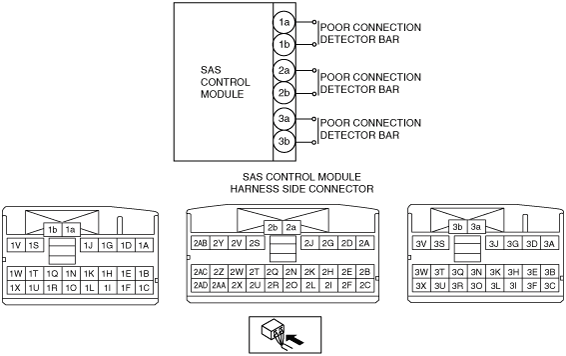
System Wiring Diagram
am3uuw00007561
|
Diagnostic Procedure
|
Step |
Inspection |
Action |
|
|---|---|---|---|
|
1
|
PERFORM MALFUNCTION DIAGNOSIS USING FLOWCHART
• Is the malfunction diagnosis performed using the flowchart? (See FLOWCHART.)
|
Yes
|
Go to the next step.
|
|
No
|
Re-perform the malfunction diagnosis using the flowchart. (See FLOWCHART.)
|
||
|
2
|
INSPECT SAS CONTROL MODULE CONNECTORS CONNECTION CONDITION
• Switch the ignition to off.
• Disconnect the negative battery cable and wait for 1 min or more.
• Remove the console. (See CONSOLE REMOVAL/INSTALLATION.)
• Are all SAS control module connectors securely connected?
|
Yes
|
Go to the next step.
|
|
No
|
Reconnect the SAS control module connectors properly.
Go to Step 4.
|
||
|
3
|
VERIFY PARTIALLY DISCONNECTED DETECTION BAR OF SAS CONTROL MODULE CONNECTOR
• Disconnect the SAS control module connectors.
• Verify the condition of the poorly connected detector bars of the SAS control module connectors. (Corrosion, damage, and disconnected pins)
• Are the poorly connected detector bars of the SAS control module connectors normal?
|
Yes
|
Go to the next step.
|
|
No
|
Replace the SAS control module connector cover, then go to the next step. (See SAS CONTROL MODULE CONNECTOR COVER REMOVAL/INSTALLATION.)
|
||
|
4
|
PERFORM DTC INSPECTION FOR SAS CONTROL MODULE
• Reconnect all disconnected connectors.
• Connect the negative battery cable.
• Switch the ignition to ON.
• Clear the DTC for the SAS control module using the M-MDS. (See CLEARING DTC.)
• Perform the DTC inspection for the SAS control module using the M-MDS. (See DTC INSPECTION.)
• Are the same DTCs present?
|
Yes
|
Replace the SAS control module connector cover, then go to the next step. (See SAS CONTROL MODULE CONNECTOR COVER REMOVAL/INSTALLATION.)
|
|
No
|
DTC troubleshooting completed.
|
||
|
5
|
PERFORM DTC INSPECTION FOR SAS CONTROL MODULE
• Reconnect all disconnected connectors.
• Connect the negative battery cable.
• Switch the ignition to ON.
• Clear the DTC for the SAS control module using the M-MDS. (See CLEARING DTC.)
• Perform the DTC inspection for the SAS control module using the M-MDS. (See DTC INSPECTION.)
• Are the same DTCs present?
|
Yes
|
Replace the SAS control module.
|
|
No
|
DTC troubleshooting completed.
|
||