 |
am3uuw00002995
CLOCK SWITCH INSPECTION
id092200015700
1. Disconnect the negative battery cable.
(See BATTERY REMOVAL/INSTALLATION [MZR 2.0, MZR 2.5].)
2. Remove the clock switch. (See HAZARD WARNING SWITCH REMOVAL/INSTALLATION.)
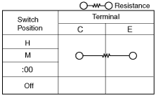
3. Verify resistance between the clock switch terminals.
am3uuw00002995
|
am3uuw00003002
|
Between the terminal C—E resistance
|
Switch position |
Resistance (ohm) |
|---|---|
|
H
|
48.45—53.55
|
|
M
|
86.45—95.55
|
|
:00
|
142.5—157.5
|
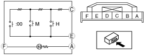
4. Connect the positive battery to the clock switch terminal A, the negative battery to the clock switch terminal F.
5. Verify the LED illuminates.