 |
am3zzw00010029
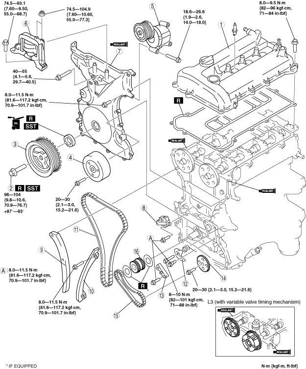
TIMING CHAIN REMOVAL/INSTALLATION [LF, L3]
id0110a2801000
1. Remove the following parts.
2. Disconnect the negative battery cable.
3. Disconnect the ventilation hose.
4. Remove the following parts.
5. Remove in the order indicated in the table.
6. Install in the reverse order of removal.
7. Start the engine.
8. Inspect the following and adjust if necessary.
am3zzw00010029
|
|
1
|
Cylinder head cover
|
|
2
|
Crankshaft pulley lock bolt
|
|
3
|
Crankshaft pulley
|
|
4
|
Water pump pulley
|
|
5
|
Drive belt auto tensioner
|
|
6
|
No.3 engine mount rubber and No.3 engine joint bracket
|
|
7
|
Engine front cover
|
|
8
|
Chain tensioner
(See Chain Tensioner Removal Note.)
|
|
9
|
Tensioner arm
|
|
10
|
Chain guide
|
|
11
|
Timing chain
|
|
12
|
Oil pump chain tensioner
|
|
13
|
Oil pump chain guide
|
|
14
|
Oil pump sprocket
|
|
15
|
Oil pump chain
|
|
16
|
Crankshaft sprocket
|
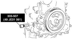
Crankshaft Pulley Lock Bolt Removal Note
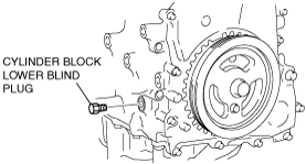
1. Remove the cylinder block lower blind plug.
2. Install the SST.
am3zzw00010030
|
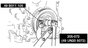
3. Turn the crankshaft clockwise the crankshaft is in the No.1 cylinder TDC position (until the balance weight is attached to the SST).
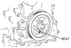
4. Hold the crankshaft pulley using the SSTs.
am3zzw00010031
|
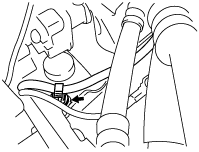
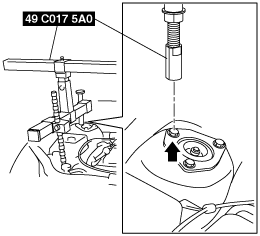
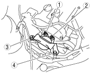
No.3 Engine Mount Rubber Removal Note
1. To install the front shaft (RH) of the SST (49 C017 5A0), remove the clip shown the figure.
am3zzw00010032
|
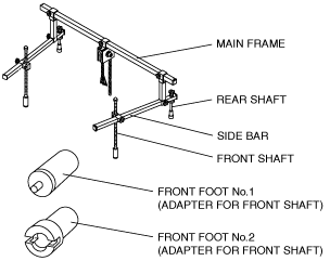
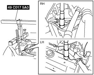
2. Install the SST using the following procedure.
am3zzw00010033
|
am3zzw00010034
|
am3zzw00010035
|
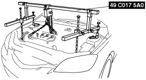
3. Suspend the engine using the SST.
am3zzw00010036
|
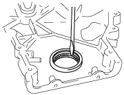
Engine Front Cover Removal Note
1. Remove the oil seal using a screwdriver as shown in the figure.
am3zzw00010037
|
Chain Tensioner Removal Note
1. Unlock the chain tensioner ratchet using a suitable screw driver or equivalent tool.
am3zzw00010038
|
2. Slowly compress the tensioner piston.
3. Hold the tensioner piston using a 1.5 mm {0.059 in} wire or paper clip.
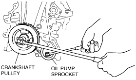
Oil Pump Sprocket Removal Note
1. Temporarily install the crankshaft pulley and crankshaft pulley lock bolt to the crankshaft, and lock the oil pump against rotation as shown in figure.
amxuuw00000712
|
2. Remove the oil pump sprocket, and then remove the crankshaft pulley and crankshaft pulley lock bolt.
Oil Pump Sprocket Installation Note
1. Temporarily install the crankshaft pulley and crankshaft pulley lock bolt to the crankshaft, and lock the oil pump against rotation as shown in figure.
amxuuw00000712
|
2. Install the oil pump sprocket, and then remove the crankshaft pulley and crankshaft pulley lock bolt.
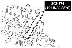
Timing Chain Installation Note
1. Install the SST to the camshaft as shown in the figure.
am3zzw00010039
|
2. Install the timing chain.
3. Remove the retaining wire or paper clip from the auto tensioner to apply tension to the timing chain.
Engine Front Cover Installation Note
1. Apply silicone sealant to the engine front cover as shown in the figure.
am3uuw00001064
|
2. Install the engine front cover bolts in the order shown in the figure.
am3zzw00010040
|
|
Bolt No. |
Tightening torque |
|---|---|
|
1—18
|
8.0—11.5 N·m{81.6—117.2 kgf·cm, 70.9—101.7 in·lbf}
|
|
19—22
|
40—55 N·m {4.1—5.6 kgf·m, 29.7—40.5 ft·lbf}
|
|
23
|
20—30 N·m {2.1—3.0 kgf·m, 14.8—22.1 ft·lbf}
|
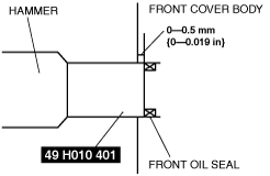
3. Apply clean engine oil to the oil seal.
4. Push the oil seal slightly in by hand.
5. Compress the oil seal using the SST and a hammer.
am3zzw00010041
|
am3zzw00010042
|
No.3 Engine Mount Rubber and No.3 Engine Mount Bracket Installation Note
1. Tighten the stud bolt of the No.3 engine mount bracket.
am3zzw00010043
|
2. Hand-tighten the No.3 engine mount rubber and No.3 engine mount bracket.
3. Tighten the bolts and nuts in the order as shown in the figure.
am3zzw00010044
|
Crankshaft Pulley Lock Bolt Installation Note
1. Install the SST to the camshaft as shown in the figure.
am3zzw00010039
|
2. Turn the crankshaft clockwise until the crankshaft is in the No.1 cylinder TDC position (until the balance weight is attached to the SST).
3. Install the M6 x 1.0 bolt in by hand.
am3zzw00010045
|
4. Hold the crankshaft pulley using the SST.
am3zzw00010031
|
5. Tighten the crankshaft pulley lock bolt in the order shown with the following two steps using the SST (49 D032 316).
6. Remove the M6 x 1.0 bolt.
7. Remove the SST from the camshaft.
8. Remove the SST from the cylinder block lower blind plug.
9. Rotate the crankshaft clockwise two turns until the TDC position.
10. Install the cylinder block lower blind plug.
am3zzw00010046
|
Cylinder Head Cover Installation Note
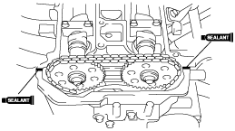
1. Apply silicone sealant to the mating faces as shown in the figure.
am3zzw00010047
|
2. Install the cylinder head cover with a new gasket.
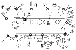
3. Tighten the bolts in the order shown in the figure.
am3zzw00010048
|