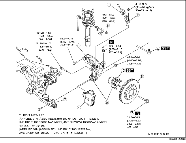
1. Remove in the order indicated in the table.
2. Install in the reverse order of removal.
3. After installation, inspect the front wheel alignment and adjust it if necessary.
(See FRONT WHEEL ALIGNMENT.)
|
1
|
ABS wheel-speed sensor connector
|
|
2
|
ABS wheel-speed sensor
|
|
3
|
Lockbolt
(See Lockbolt Installation Note.)
|
|
4
|
Brake caliper component
(See Brake Caliper Removal Note.)
|
|
5
|
Disc plate
|
|
6
|
Tie-rod end ball joint
|
|
7
|
Front lower arm ball joint
|
|
8
|
Stabilizer control link upper nut
|
|
9
|
Wheel hub, steering knuckle component
|
|
10
|
Wheel hub component
|
|
11
|
Steering knuckle
|
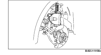
1. Remove the brake caliper component from the steering knuckle and suspend it out of the way using a cable.
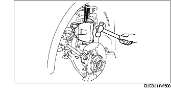
1. Separate the shock absorber from the wheel hub, steering knuckle component by tapping the upper part of the steering knuckle with a hammer.
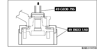
1. Remove the wheel hub component using the SSTs.
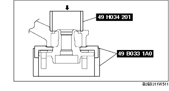
1. Install the wheel hub component using the SSTs.
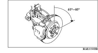
1. Install a new lockbolt and tighten it.
2. Mark the lockbolt at one point and tighten it further until the marking has moved 85°-95°.