1. Verify that the starter operates only when the ignition switch is turned to the START position with the selector lever in P or N position.
2. Verify that the back-up lights illuminate when shifted to R position with the ignition switch at the ON position.
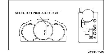
3. Verify that the positions of the selector lever and the indicator are aligned.
1. Remove the battery cover. (See BATTERY REMOVAL/INSTALLATION [ZY, Z6].) (See BATTERY REMOVAL/INSTALLATION [LF, L3].)
2. Disconnect the negative battery cable.
3. Remove the under cover.
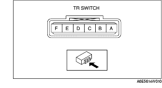
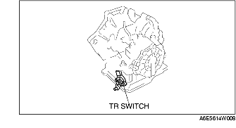
4. Disconnect the TR switch connector.
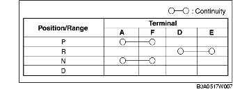
5. Verify that the continuity is as indicated in the table.
6. Reinspect for continuity at TR switch.
7. Connect the TR switch connector.
8. Install the under cover.
9. Connect the negative battery cable.
10. Install the battery cover. (See BATTERY REMOVAL/INSTALLATION [ZY, Z6].) (See BATTERY REMOVAL/INSTALLATION [LF, L3].)
1. Remove the battery cover. (See BATTERY REMOVAL/INSTALLATION [ZY, Z6].) (See BATTERY REMOVAL/INSTALLATION [LF, L3].)
2. Disconnect the negative battery cable.
3. Remove the under cover.
4. Disconnect the TR switch connector.
5. Measure the resistance between the following terminals.
6. Connect the TR switch connector.
7. Install the under cover.
8. Connect the negative battery cable.
9. Install the battery cover. (See BATTERY REMOVAL/INSTALLATION [ZY, Z6].) (See BATTERY REMOVAL/INSTALLATION [LF, L3].)