1. Remove the battery cover. (See BATTERY REMOVAL/INSTALLATION [ZY, Z6].) (See BATTERY REMOVAL/INSTALLATION [LF, L3].)
2. Disconnect the negative battery cable.
3. Remove the under cover.
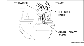
4. Disconnect the TR switch connector.
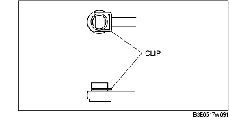
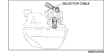
5. Remove the clip and disconnect the selector cable.
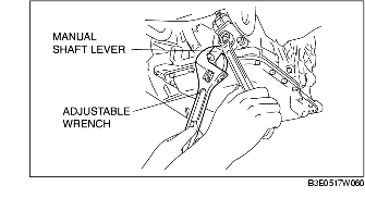
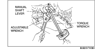
6. Set the adjustable wrench as shown in the figure to hold the manual shaft lever.
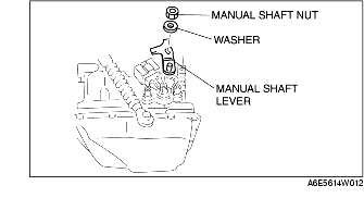
7. Remove the manual shaft nut and washer.
8. Remove the manual shaft lever.
9. Remove the TR switch.
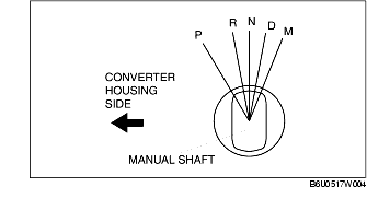
10. Rotate the manual shaft to the converter housing side fully, then return two notches to set the N position.
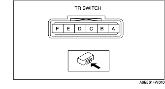
11. Turn the protrusion between the TR switch terminals B and C until the resistance becomes 750 ohms.
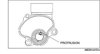
12. Install the TR switch while aligning the protrusion and groove as shown in the figure.
13. Hand-tighten the TR switch mounting bolts.
14. Inspect the resistance between the TR switch terminals B and C.
15. Tighten the TR switch mounting bolts.
16. Install the manual shaft lever and the washer.
17. Set the adjustable wrench as shown in the figure to hold the manual shaft lever, and tighten the manual shaft nut.
18. Install the clip to the selector cable as shown in the figure.
19. Shift the selector lever to P position.
20. Turn the manual shaft lever to P position.
21. Connect the selector cable.
22. Inspect for continuity at the TR switch. (See TRANSAXLE RANGE (TR) SWITCH INSPECTION.)
23. Connect the TR switch connector.
24. Install the under cover.
25. Connect the negative battery cable.
26. Install the battery cover. (See BATTERY REMOVAL/INSTALLATION [ZY, Z6].) (See BATTERY REMOVAL/INSTALLATION [LF, L3].)
27. Inspect operation of the TR switch. (See TRANSAXLE RANGE (TR) SWITCH INSPECTION.)