 |
am3zzw00009528
AUTOMATIC TRANSAXLE REMOVAL/INSTALLATION [LF, L3]
id0517008024b2
1. Remove the battery duct and battery cover. (See BATTERY REMOVAL/INSTALLATION [LF, L3].)
2. Disconnect the negative battery cable.
3. Remove the following parts.
4. Drain the ATF. (See AUTOMATIC TRANSAXLE FLUID (ATF) REPLACEMENT.)
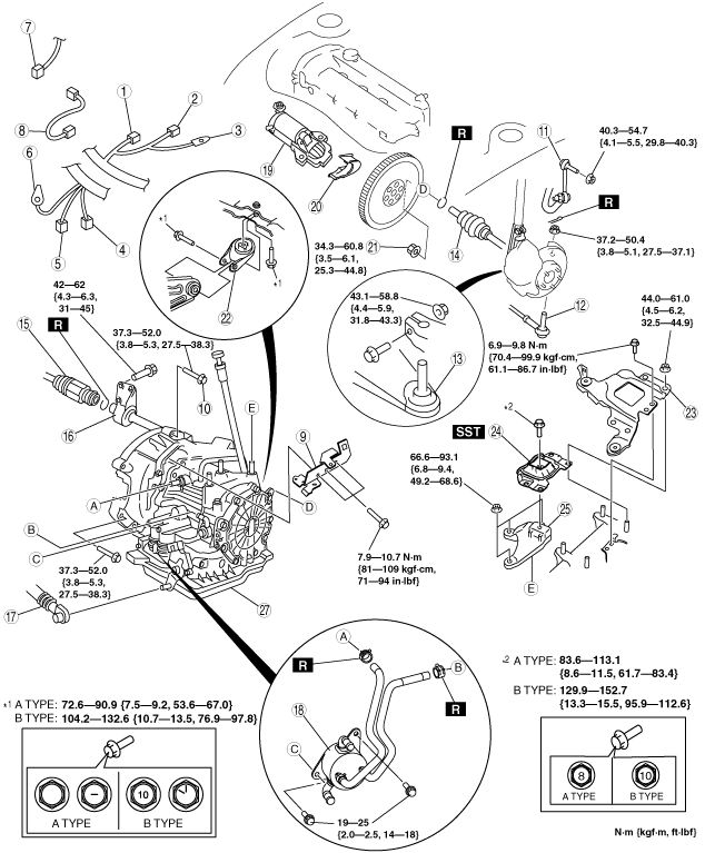
5. Remove in the order indicated in the table.
6. Install in the reverse order of removal.
7. Add ATF to the specified level. (See AUTOMATIC TRANSAXLE FLUID (ATF) REPLACEMENT.)
8. Perform the following test. (See MECHANICAL SYSTEM TEST.) (See ROAD TEST.)
|
Service item |
Test item |
|||
|---|---|---|---|---|
|
Line pressure test |
Stall test |
Time lag test |
Road test |
|
|
ATX replacement
|
X
|
|
|
|
|
ATX overhaul
|
X
|
X
|
X
|
X
|
|
Torque converter replacement
|
X
|
X
|
|
|
|
Oil pump replacement
|
X
|
|
|
|
|
Clutch system replacement
|
X
|
|
X
|
X
|
am3zzw00009528
|
|
1
|
Input/turbine speed sensor connector
|
|
2
|
VSS connector
|
|
3
|
GND wiring harness
|
|
4
|
Transaxle connector
|
|
5
|
TR switch connector
|
|
6
|
GND wiring harness
|
|
7
|
Oil pressure switch connector (for oil filter)
|
|
8
|
Oil pressure switch connector (for L3 ATX)
|
|
9
|
Harness bracket
|
|
10
|
Transaxle mounting bolt (upper side)
|
|
11
|
Stabilizer control link
|
|
12
|
Tie-rod end ball joint
|
|
13
|
Lower arm ball joint
|
|
14
|
Drive shaft
|
|
15
|
Drive shaft
|
|
16
|
Joint shaft
|
|
17
|
Selector cable
|
|
18
|
Oil cooler
|
|
19
|
Starter
|
|
20
|
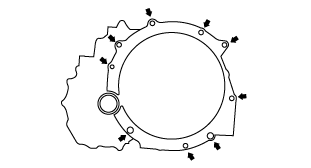
End plate cover
|
|
21
|
Torque converter installation nuts
|
|
22
|
No.1 engine mount rubber
|
|
23
|
Battery tray bracket
|
|
24
|
No.4 engine mount rubber
|
|
25
|
No.4 engine mount bracket
|
|
26
|
Transaxle mounting bolt (lower side)
|
|
27
|
Transaxle
(See Transaxle Removal Note.)
(See Transaxle Installation Note.)
|
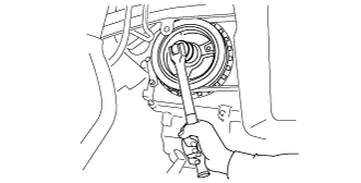
Torque Converter Nuts Removal Note
1. Hold the crankshaft pulley to prevent the drive plate from rotating.
am3zzw00009529
|
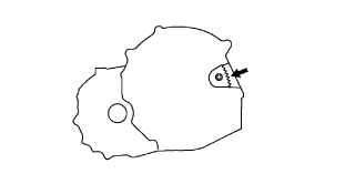
2. Remove the torque converter nuts from the starter installation hole.
am3zzw00009530
|
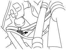
No.4 Engine Mount Removal Note
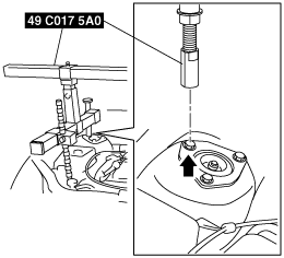
1. To install the front shaft (RH) of the SST (49 C017 5A0), remove the clip shown in the figure.
am3zzw00009531
|
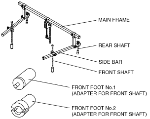
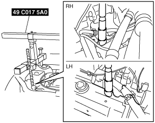
2. Install the SST using the following procedure.
am3zzw00009532
|
am3zzw00009533
|
am3zzw00009534
|
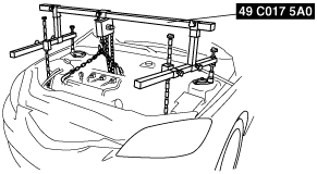
3. Support the engine using the SST.
am3zzw00009535
|
4. Remove the battery tray bracket, No.4 engine mount rubber and bracket.
Transaxle Removal Note
1. Adjust the SST and lean the engine toward the transaxle.
am3zzw00009535
|
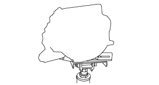
2. Support the transaxle on a jack.
3. Remove the transaxle mounting bolts.
4. Remove the transaxle.
am3zzw00009536
|
Transaxle Installation Note
1. Set the transaxle on a jack and lift it.
2. Install the transaxle mounting bolts.
am3zzw00009537
|
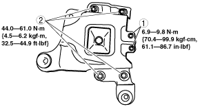
No.1 Engine Mount and No.4 Engine Mount Installation Note
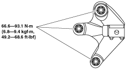
1. Install the No.4 engine mount bracket on the transaxle case and tighten nuts.
am3zzw00009538
|
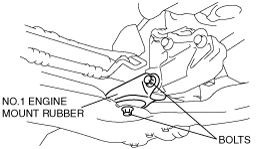
2. Install the No.1 engine mount rubber to the crossmember and temporarily tighten bolts.
am3zzw00009539
|
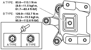
3. Place the No.4 engine mount rubber with the body stud bolts passing through the holes and tighten the bolt in the figure.
am3zzw00009540
|
4. Place the battery tray bracket on the No.4 engine mount rubber with body stud bolts passing through the holes and tighten bolts and nuts in the order as shown in the figure.
am3zzw00009541
|
5. Remove the SST (49 C017 5A0).
6. Install the clip as shown in the figure.
am3zzw00009531
|
7. Fully tighten the bolts
c3u515zw3204
|
Torque Converter Nuts Installation Note
1. Hold the crankshaft pulley to prevent the drive plate from rotating.
am3zzw00009529
|
2. Tighten the torque converter mounting nuts.
am3zzw00009530
|