 |
am6zzw00005782
EXHAUST SYSTEM REMOVAL/INSTALLATION [MZR-CD 2.2]
id0115f2800200
|
STEP |
ACTION |
PAGE/CONDITION |
|---|---|---|
|
1
|
Replace the oxidation catalytic converter.
|
–
|
|
2
|
Switch the ignition to on.
|
–
|
|
3
|
Perform diesel particulate filter data reset procedure.
|
|
|
4
|
Start the engine.
|
Verify that the MIL does not illuminate.
|
|
5
|
Switch the ignition to off.
|
–
|
|
6
|
Switch the ignition to on (Engine off).
|
–
|
|
7
|
Perform KOEO self-test procedure.
|
|
|
8
|
Perform exhaust gas pressure sensor data reset procedure.
|
|
|
9
|
Switch the ignition to off.
|
–
|
|
10
|
Wait for 20 s.
|
–
|
|
11
|
Start the engine.
|
–
|
|
12
|
Perform KOEO self-test procedure.
|
Warm up until the exhaust gas temperature (EXHTEMP1, EXHTEMP2 PID) is 100 °C {212 °F} or more.
|
|
13
|
Perform fuel injector injection amount correction procedure.
|
Engine coolant temperature 65—95 °C {149—203 °F}.
Intake air temperature 15—65 °C {59—149 °F}.
Fuel temperature 30—60 °C {86—140 °F}.
|
|
14
|
Perform diesel particulate filter assessment procedure.
|
Engine coolant temperature 60 °C {140 °F} or more.
|
|
15
|
Perform diesel particulate filter regeneration procedure.
|
Engine coolant temperature 70 °C {158 °F} or more.
|
|
16
|
Using the following PIDs, verify that the diesel particulate filter regeneration has been completed.
― REG_REQ_A
― REG_REQ_F
|
|
|
17
|
Perform after repair procedure.
|
|
|
18
|
Switch the ignition to off.
|
–
|
1. Disconnect the negative battery cable. (See BATTERY REMOVAL/INSTALLATION [MZR-CD 2.2].)
2. Remove the engine cover. (See ENGINE COVER REMOVAL/INSTALLATION [MZR-CD 2.2].)
3. Remove the aerodynamic under cover No.2. (See AERODYNAMIC UNDER COVER NO.2 REMOVAL/INSTALLATION.)
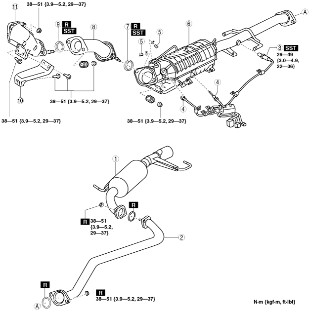
4. Remove in the order indicated in the table.
5. Remove the exhaust system insulator. (See Exhaust System Insulator Removal/Installation Note.)
6. Install in the reverse order of removal.
7. Start the engine and:
Step 1
am6zzw00005782
|
|
1
|
Main silencer
|
|
2
|
Middle pipe
|
|
3
|
A/F sensor
|
|
4
|
Exhaust gas temperature sensor
|
|
5
|
Exhaust gas pressure hose
|
|
6
|
Oxidation catalytic converter (built-in diesel particulate filter)
|
|
7
|
Seal ring (front pipe side)
(See Seal Ring Removal Note.)
|
|
8
|
Front pipe
|
|
9
|
Seal ring (joint pipe side)
(See Seal Ring Removal Note.)
|
|
10
|
Joint pipe bracket
|
|
11
|
Joint pipe
(See Joint Pipe Removal Note.)
|
Step 2
am6zzw00005783
|
|
1
|
Joint pipe gasket
|
|
2
|
Exhaust manifold insulator (lower)
|
|
3
|
Exhaust manifold insulator (upper)
|
|
4
|
Oil inlet pipe
|
|
5
|
Oil outlet pipe
|
|
6
|
Water hose
|
|
7
|
Turbocharger
(See Turbocharger Removal Note.)
|
|
8
|
Water pipe
(See Water Pipe Removal Note.)
|
|
9
|
Exhaust manifold
|
|
10
|
Exhaust manifold gasket
|
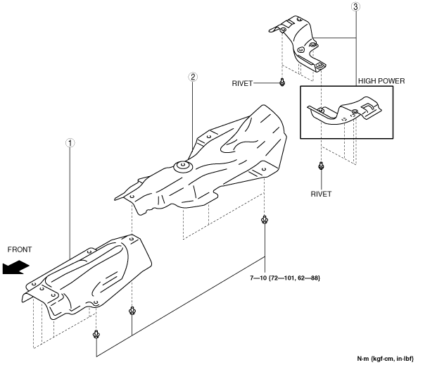
Exhaust System Insulator Removal/Installation Note
1. Remove in the order indicated in the table.
2. Install in the reverse order of removal.
am6zzw00004374
|
|
1
|
Insulator (front)
|
|
2
|
Insulator (middle)
|
|
3
|
Insulator (rear)
|
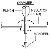
Insulator (rear) removal note
1. Push out the mandrel using a hammer and punch (2—2.8 mm {0.08—0.11 in} diameter).
am6zzw00004375
|
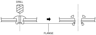
2. Remove the flange using a drill (5 mm {0.20 in} drill bit).
am6zzw00004376
|
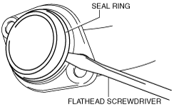
Seal Ring Removal Note
1. Remove the seal ring using a flathead screwdriver being careful not to damage the pipe.
am6zzw00005784
|
Joint Pipe Removal Note
1. Remove the battery and battery tray. (See BATTERY REMOVAL/INSTALLATION [MZR-CD 2.2].)
2. Remove the turbocharger air outlet pipe No.2. (See INTAKE-AIR SYSTEM REMOVAL/INSTALLATION [MZR-CD 2.2].)
3. Remove the joint pipe.
Exhaust Manifold Insulator (Upper) Removal Note
1. Remove the air inlet pipe No.1. (See INTAKE-AIR SYSTEM REMOVAL/INSTALLATION [MZR-CD 2.2].)
2. Remove the air inlet pipe No.2. (See INTAKE-AIR SYSTEM REMOVAL/INSTALLATION [MZR-CD 2.2].)
3. Remove the turbocharger air outlet pipe No.1. (See INTAKE-AIR SYSTEM REMOVAL/INSTALLATION [MZR-CD 2.2].)
4. Remove the Turbocharger air inlet pipe bracket. (See INTAKE-AIR SYSTEM REMOVAL/INSTALLATION [MZR-CD 2.2].)
5. Remove the exhaust manifold insulator (upper).
Water Pipe Removal Note
1. Drain the engine coolant. (See ENGINE COOLANT REPLACEMENT [MZR-CD 2.2].)
2. Remove the water pipe.
Turbocharger Removal Note
1. Disconnect the variable boost control (VBC) actuator connector.
2. Disconnect the vacuum hose from the VBC actuator.
3. Remove the turbocharger and water pipe as a single unit.
4. Remove the turbocharger.
Exhaust Manifold Removal Note
1. Remove the EGR cooler and EGR cooler bypass valve component. (See EGR COOLER REMOVAL/INSTALLATION [MZR-CD 2.2].)
2. Remove the exhaust manifold.
Exhaust Manifold Installation Note
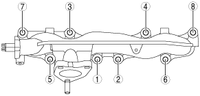
1. Tighten the exhaust manifold installation nuts in the order shown.
am6zzw00005785
|
Joint Pipe Gasket Installation Note
1. To come to position that the claw of the gasket shows in figure, it installs it.
am6zzw00004524
|
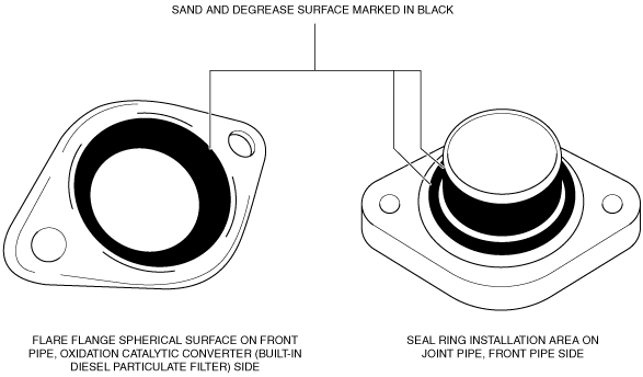
Flange Surface Installation Note
1. Sand the surface shown in the figure using sandpaper and remove sanding residue, accumulated matter, and friction marks.
2. Degrease the sanded surface.
am6zzw00011900
|
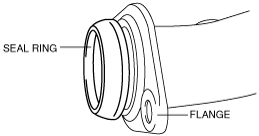
Seal Ring Installation Note (Joint Pipe Side)
1. Temporarily install the seal ring to the pipe so that the seal ring is even with the flange.
am6zzw00003446
|
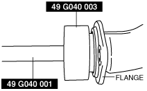
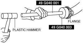
2. Install the SST to the seal ring so that the SST is even with the flange.
am6zzw00005786
|
3. Press in the seal ring by tapping the SST using a plastic hammer until the seal ring contacts the flange.
am6zzw00005787
|
Seal Ring Installation Note (Front Pipe Side)
1. Temporarily install the seal ring to the pipe so that the seal ring is even with the flange.
am6zzw00003446
|
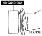
2. Install the SST to the seal ring so that the SST is even with the flange.
am6zzw00005789
|
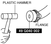
3. Press in the seal ring by tapping the SST using a plastic hammer until the seal ring contacts the flange.
am6zzw00004280
|