 |
am6zzw00006345
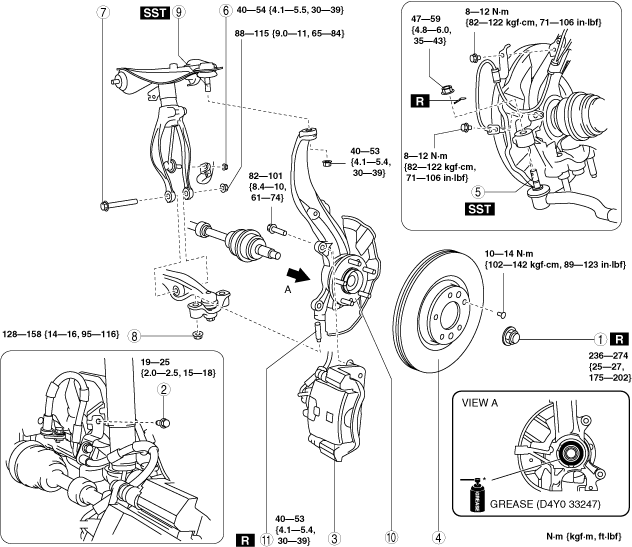
WHEEL HUB, STEERING KNUCKLE REMOVAL/INSTALLATION
id031100800400
1. When working on the right side of the vehicle, disconnect the front auto leveling sensor link. (Vehicle with discharge headlight system) (See AUTO LEVELING SENSOR REMOVAL/INSTALLATION.)
2. Remove in the order indicated in the table.
3. Install in the reverse order of removal.
4. After installation, inspect the front wheel alignment and adjust it if necessary. (See FRONT WHEEL ALIGNMENT [European (L.H.D., U.K.) Specs.].) (See FRONT WHEEL ALIGNMENT [Australian Specs. and General (L.H.D., R.H.D.) Specs.].)
am6zzw00006345
|
|
1
|
Locknut
|
|
2
|
Bolt (brake hose)
|
|
3
|
Brake caliper component
|
|
4
|
Disc plate
|
|
5
|
Tie-rod end ball joint
|
|
6
|
Front stabilizer control link lower side bolt
|
|
7
|
Damper fork lower side bolt
|
|
8
|
Nut (lower arm)
(See Nut (Lower Arm) Removal Note.)
|
|
9
|
Upper arm ball joint
|
|
10
|
Wheel hub, steering knuckle component
|
|
11
|
Stud bolt
|
Brake Caliper Component Removal Note
1. Remove the brake caliper component and suspend it out of the way using a cable.
Nut (Lower Arm) Removal Note
Wheel Hub, Steering Knuckle Component Installation Note
1. Apply grease (D4Y0 33247) to the wheel bearing inner race and drive shaft contact surface (Area A in figure).
am6xuw00002787
|
2. Install the wheel hub, steering knuckle component.
