|
am6zzw00006190
FRONT CROSSMEMBER REMOVAL/INSTALLATION
id021300801000
1. Remove the steering shaft cover and disconnect the steering shaft from the steering gear and linkage, and then remove the steering dust cover. (See STEERING WHEEL AND COLUMN REMOVAL/INSTALLATION [WITHOUT ADVANCED KEYLESS ENTRY AND PUSH BUTTON START SYSTEM].) (See STEERING WHEEL AND COLUMN REMOVAL/INSTALLATION [WITH ADVANCED KEYLESS ENTRY AND PUSH BUTTON START SYSTEM].) (See STEERING GEAR AND LINKAGE REMOVAL/INSTALLATION [L.H.D.].) (See STEERING GEAR AND LINKAGE REMOVAL/INSTALLATION [R.H.D.].)
2. Remove the aerodynamic under cover No. 1 and No. 2. (See AERODYNAMIC UNDER COVER NO.1 REMOVAL/INSTALLATION.) (See AERODYNAMIC UNDER COVER NO.2 REMOVAL/INSTALLATION.)
3. Remove the front auto leveling sensor. (Vehicle with discharge headlight system) (See AUTO LEVELING SENSOR REMOVAL/INSTALLATION.)
4. Remove the transverse member. (See TRANSVERSE MEMBER REMOVAL/INSTALLATION.)
5. Remove in the order indicated in the table.
6. Install in the reverse order of removal.
7. Inspect the front wheel alignment. (See FRONT WHEEL ALIGNMENT [European (L.H.D., U.K.) Specs.].)(See FRONT WHEEL ALIGNMENT [Australian Specs. and General (L.H.D., R.H.D.) Specs.].)
8. Set the EPS system neutral position. (See EPS SYSTEM NEUTRAL POSITION SETTING.)
am6zzw00006190
|
|
1
|
Front ABS wheel-speed sensor
|
|
2
|
Brake hose bracket bolt
|
|
3
|
Tie-rod end
(See Tie-rod End Removal Note.)
|
|
4
|
Front shock absorber lower side bolt
|
|
5
|
Front lower arm outer side nut
|
|
6
|
No.1 engine mount center bolt
|
|
7
|
Front crossmember component
|
|
8
|
Steering gear and linkage
|
|
9
|
Front stabilizer
|
|
10
|
Front lower arm
|
|
11
|
No. 1 engine mount
|
|
12
|
Front crossmember
|
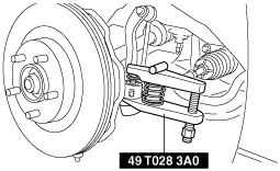
Tie-rod End Removal Note
1. Detach the tie-rod end from the steering knuckle using the SST.
am6zzw00001953
|
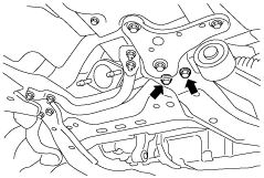
Front Crossmember Component Removal Note
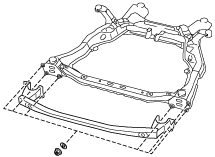
1. Remove the front lower arm (front) lower side bolts.
am6zzw00001954
|
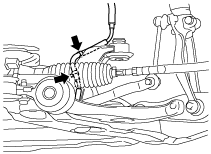
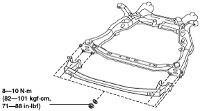
2. Remove the radiator hose bracket bolt.
am6zzw00001955
|
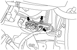
3. Detach the charcoal canister hose clips from the front crossmember.
am6zzw00002496
|
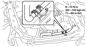
4. Disconnect the EPS control module connectors from the EPS control module. (See EPS CONTROL MODULE REMOVAL/INSTALLATION.)
am6zzw00002497
|
5. Detach the extension.
am6zzw00001958
|
6. Support the crossmember component with a jack.
am6zzw00001959
|
7. Remove the crossmember bracket.
8. Remove the front crossmember component.
Front Crossmember Component Installation Note
1. Jack up the front crossmember component slowly.
am6zzw00001959
|
2. Install the EPS motor connector to the EPS control module. (See EPS CONTROL MODULE REMOVAL/INSTALLATION.)
3. Install the extension to the front crossmember.
am6zzw00001960
|
4. Install the charcoal canister hose clips to the front crossmember.
5. Tighten the radiator hose bracket bolt.
am6zzw00001961
|
6. Install the front crossmember component, and tighten the nuts to the specified torque.