STEP
INSPECTION
ACTION
1
CONFIRM INSTRUMENT CLUSTER DTC
• Retrieve the instrument cluster DTC using the M-MDS.
• Is the DTC U0415:92 present?
Yes
Go to the next step.
No
Go to Step 11.
2
CONFIRM ABS HU/CM DTC
• Retrieve the ABS HU/CM DTC using the M-MDS.
(See ON-BOARD DIAGNOSIS [ABS].)
• Are any DTCs present?
Yes
Go to the applicable DTC inspection.
(See ON-BOARD DIAGNOSIS [ABS]s.)
No
If communication error message is displayed on the M-MDS screen:
• Go to the next step.
If communication error message is not displayed:
• Go to Step 7.
3
INSPECT FOR CONNECTION OF ABS HU/CM CONNECTOR
• Inspect for connection of the ABS HU/CM connector.
• Is the ABS connector connected securely?
Yes
Go to the next step.
No
Connect the ABS HU/CM connector securely, then go to Step 7.
4
INSPECT ABS POWER SUPPLY FUSE
• Inspect the ABS power supply fuse.
• Is the fuse normal?
Yes
Go to the next step.
No
Inspect the blown fuse’s circuit for short to ground.
Repair or replace the wiring harness for a possible short to ground as necessary.
Install appropriate amperage fuse.
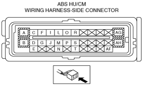
*5
VERIFY WHETHER MALFUNCTION IS IN WIRING HARNESS (BETWEEN ABS HU/CM POWER SUPPLY AND ABS HU/CM FOR CONTINUITY) OR ELSEWHERE
• Switch the ignition to ON.
• Measure the voltage at the ABS HU/CM terminal AF (wiring harness-side).
• Is the voltage approx. 12 V?
Yes
Go to the next step.
No
Inspect for open circuit between ABS HU/CM and ignition.
Repair or replace the wiring harness for a possible open circuit as necessary.
*6
VERIFY WHETHER MALFUNCTION IS IN WIRING HARNESS (BETWEEN ABS HU/CM AND GND FOR CONTINUITY) OR ABS HU/CM
• Switch the ignition to off.
• Disconnect the ABS HU/CM connector.
• Inspect for continuity between ABS HU/CM terminal A (wiring harness-side) and body ground.
• Is there continuity?
Yes
Replace the ABS HU/CM (internal malfunction).
No
Repair or replace the wiring harness for a possible open circuit and poor contact in GND point.
7
VERIFY WHETHER MALFUNCTION IS IN ABS HU/CM IGNITION POWER SUPPLY SYSTEM (TERMINAL AF) OR ELSEWHERE
• Switch the ignition to ON.
• Access the ABS HU/CM PID VPWR using the M-MDS.
(See ON-BOARD DIAGNOSIS [ABS].)
• Is the monitored value above 10 V?
Yes
Go to Step 11.
No
Go to the next step.
8
INSPECT BATTERY
• Inspect the battery.
• Is the battery normal?
Yes
Go to the next step.
No
Recharge or replace the battery, then go to the next step.
9
INSPECT CHARGING SYSTEM WITH ELECTRICAL LOAD OPERATING
• Is the battery voltage normal with electrical load (A/C, headlight, rear window defroster, etc.) on the engine idling?
Yes
Go to the next step.
No
Inspect the charging system (drive belt tension, generator, etc.).
Repair or replace any malfunctioning parts according to the inspection result.
*10
VERIFY WHETHER MALFUNCTION IS IN WIRING HARNESS (BETWEEN ABS HU/CM POWER SUPPLY AND ABS HU/CM FOR CONTINUITY) OR ELSEWHERE
• Switch the ignition to ON.
• Measure the voltage at the ABS HU/CM terminal AF (wiring harness-side).
• Is the voltage approx. 12 V?
Yes
Replace the ABS HU/CM (internal malfunction).
No
Inspect for open circuit between ABS HU/CM and ignition.
Repair or replace the wiring harness for a possible open circuit as necessary.
11
VERIFY WHERE MALFUNCTION IS IN INSTRUMENT CLUSTER OR ABS HU/CM
• Connect the M-MDS to the DLC-2.
• Turn off all warning lights and indicator lights using the instrument cluster PID WL+IL of active command modes.
• Does the ABS warning light turn stay on?
Yes
Replace the instrument cluster.
No
Replace the ABS HU/CM (internal malfunction).