 |
am6zzw00004929
SECONDARY CONTROL VALVE BODY INSTALLATION [FS5A-EL]
id051721807600
On-Vehicle Installation
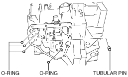
1. Install the tubular pin and new O-ring to the transaxle case.
am6zzw00004929
|
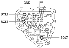
2. Install the secondary control valve body.
3. Tighten the bolts and GND as shown to install the secondary control valve body.
am6zzw00004928
|
Bolt length measured from below the head
|
Mark |
Length measured from below the head |
|---|---|
|
B
|
40mm {1.575 in}
|
|
C
|
50mm {1.967 in}
|
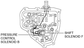
4. Connect each solenoid valve connector.
am6zzw00004927
|
Connector color (harness-side)
|
Solenoid valve |
Connector color |
|---|---|
|
Pressure control solenoid B
|
White
|
|
Shift solenoid F
|
Black
|
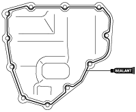
5. Apply a light coat of silicon sealant (TB1217E) to the contact surfaces of the oil cover and transaxle case.
am6zzw00004933
|
6. Install the oil cover before the applied sealant starts to harden.
7. Add the ATF. (See AUTOMATIC TRANSAXLE FLUID (ATF) REPLACEMENT [FS5A-EL].)
8. Install the aerodynamic under cover NO.2. (See AERODYNAMIC UNDER COVER NO.2 REMOVAL/INSTALLATION.)
9. Install the EPS control module. (See EPS CONTROL MODULE REMOVAL/INSTALLATION.)
10. Install the battery and battery tray. (See BATTERY REMOVAL/INSTALLATION [MZR 1.8, MZR 2.0, MZR 2.5].) (See BATTERY REMOVAL/INSTALLATION [MZR 2.0 DISI].)
11. Connect the negative battery cable.
12. Perform the “Mechanical System Test”. (See MECHANICAL SYSTEM TEST [FS5A-EL].)
13. Perform the “Road Test”. (See ROAD TEST [FS5A-EL].)