 |
am6zzw00006709
DTC B10FE:11/B10FE:13/B10FE:87/B10FE:96
id080200847200
System Malfunction Location
|
DTC |
System Malfunction Location |
|---|---|
|
M-MDS display |
|
|
B10FE:11
|
Passenger-side side air bag sensor No.1 short to body ground
|
|
B10FE:13
|
Passenger-side side air bag sensor No.1 circuit short to power supply or open line
|
|
B10FE:87
|
No response from passenger-side side air bag sensor No.1
|
|
B10FE:96
|
Passenger-side side air bag sensor No.1 internal malfunction
|
Detection Condition
Possible Causes
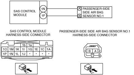
System Wiring Diagram
am6zzw00006709
|
Diagnostic Procedure
|
Step |
Inspection |
Action |
|
|---|---|---|---|
|
1
|
INSPECT PASSENGER-SIDE SIDE AIR BAG SENSOR NO.1 CONNECTOR
• Switch the ignition to off.
• Disconnect the negative battery cable and wait for 1 min or more.
• Remove the B-pillar lower trim (passenger's side).
• Disconnect the passenger-side side air bag sensor No.1 connector. (See SIDE AIR BAG SENSOR NO. 1 REMOVAL/INSTALLATION.)
• Inspect the passenger-side side air bag sensor No.1 connector. (Corrosion, damage, and disconnected pins)
• Is there any malfunction of the passenger-side side air bag sensor No.1 connector?
|
Yes
|
Replace the passenger-side side air bag sensor No.1 wiring harness.
|
|
No
|
Go to the next step.
|
||
|
2
|
INSPECT WIRING HARNESS BETWEEN SAS CONTROL MODULE AND PASSENGER-SIDE SIDE AIR BAG SENSOR NO.1
• Remove the column cover.
• Disconnect the clock spring connector.
• Remove the glove compartment.
• Disconnect the passenger-side air bag module connector.
• Disconnect the driver and passenger-side side air bag module connectors.
• Remove the C-pillar trim. (4SD)
• Remove the headliner. (5HB, WGN)
• Disconnect the driver and passenger-side curtain air bag module connectors.
• Remove the B-pillar lower trim. (4SD)
• Disconnect the driver and passenger-side pre-tensioner seat belt connectors.
• Remove the rear console.
• Disconnect the SAS control module connectors.
• Inspect the wiring harnesses between SAS control module connector terminal 1N and passenger-side side air bag sensor No.1 connector terminal A, and SAS control module connector terminal 1P and passenger-side side air bag sensor No.1 connector terminal B for the following:
• Is the wiring harness normal?
|
Yes
|
Go to the next step.
|
|
No
|
Replace the wiring harness between the SAS control module and the passenger-side side air bag sensor No.1.
|
||
|
3
|
INSPECT THE WIRING HARNESS BETWEEN THE SAS CONTROL MODULE AND PASSENGER-SIDE SIDE AIR BAG SENSOR NO.1 FOR A SHORT CIRCUIT TO THE POWER SUPPLY
• Connect the negative battery cable.
• Switch the ignition to ON with SAS control module connector and passenger-side side air bag sensor No.1 disconnected.
• Measure the voltage of SAS control module connector terminals 1N and 1P.
• Is the voltage measured?
|
Yes
|
Replace the wiring harness between the SAS control module and the passenger-side side air bag sensor No.1.
|
|
No
|
Replace the passenger-side side air bag sensor No.1, then go to the next step.
|
||
|
4
|
PERFORM SAS CONTROL MODULE DTC INSPECTION
• Switch the ignition to off.
• Disconnect the negative battery cable and wait for 1 min or more.
• Reconnect all disconnected connectors.
• Connect the negative battery cable.
• Switch the ignition to ON.
• Clear the DTC for the SAS control module using the M-MDS.
(See CLEARING DTC.)
• Perform the DTC inspection for the SAS control module using the M-MDS.
(See DTC DISPLAY.)
• Are the same DTCs present?
|
Yes
|
Replace the SAS control module.
|
|
No
|
DTC troubleshooting completed.
|
||