|
1
|
INSPECT BRAKE SWITCH CONNECTOR CONDITION
• Switch the ignition to off.
• Disconnect the negative battery cable.
• Disconnect the brake switch connector.
• Inspect the connector and terminals (corrosion, damage, pin disconnection).
• Is there any malfunction?
|
Yes
|
Repair or replace the connector or terminals, then go to Step 10.
|
|
No
|
Go to the next step.
|
|
2
|
INSPECT BRAKE SWITCH GROUND CIRCUIT FOR OPEN CIRCUIT
• Brake switch connector is disconnected.
• Inspect for continuity between brake switch terminal B (wiring harness-side) and body ground.
• Is there continuity?
|
Yes
|
Go to the next step.
|
|
No
|
Repair or replace the wiring harness for a possible open circuit, then go to Step 10.
|
|
3
|
INSPECT BRAKE SWITCH POWER SUPPLY CIRCUIT FOR OPEN CIRCUIT OR SHORT TO GROUND
• Brake switch connector is disconnected.
• Reconnect the negative battery cable.
• Measure the voltage at the brake switch terminal A (wiring harness-side).
• Is the voltage B+?
|
Yes
|
Go to the next step.
|
|
No
|
Inspect the STOP 10 A fuse.
• If the fuse is melt:
-
― Repair or replace the wiring harness for a possible short to ground.
― Replace the fuse.
• If the fuse is deterioration:
-
― Replace the fuse.
• If the fuse is normal:
-
― Repair or replace the wiring harness for a possible open circuit.
Go to Step 10.
|
|
4
|
INSPECT PCM CONNECTOR CONDITION
• Disconnect the negative battery cable.
• Disconnect the PCM connector.
• Inspect the connector and terminals (corrosion, damage, pin disconnection).
• Is there any malfunction?
|
Yes
|
Repair or replace the connector or terminals, then go to Step 10.
|
|
No
|
Go to the next step.
|
|
5
|
INSPECT KEYLESS CONTROL MODULE CONNECTOR CONDITION
• Disconnect the keyless control module connector.
• Inspect the connector and terminals (corrosion, damage, pin disconnection).
• Is there any malfunction?
|
Yes
|
Repair or replace the connector or terminals, then go to Step 10.
|
|
No
|
Go to the next step.
|
|
6
|
INSPECT BRAKE SWITCH CIRCUIT FOR SHORT TO GROUND
• Brake switch, PCM and keyless control module connectors are disconnected.
• Inspect for continuity between the following terminals (wiring harness-side) and body ground:
-
― Brake switch terminal C
― Brake switch terminal D
• Is there continuity?
|
Yes
|
Repair or replace the wiring harness for a possible short to ground, then go to Step 10.
|
|
No
|
Go to the next step.
|
|
7
|
INSPECT BRAKE SWITCH CIRCUIT FOR SHORT TO POWER SUPPLY
• Brake switch, PCM and keyless control module connectors are disconnected.
• Reconnect the negative battery cable.
• Switch the ignition to ON.
• Measure the voltage at the following terminals (wiring harness-side):
-
― Brake switch terminal C
― Brake switch terminal D
• Is there any voltage?
|
Yes
|
Repair or replace the wiring harness for a possible short to power supply, then go to Step 10.
|
|
No
|
Go to the next step.
|
|
8
|
INSPECT BRAKE SWITCH CIRCUIT FOR OPEN CIRCUIT
• Brake switch, PCM and keyless control module connectors are disconnected.
• Switch the ignition to off.
• Disconnect the negative battery cable.
• Inspect for continuity between the following terminals (wiring harness-side):
-
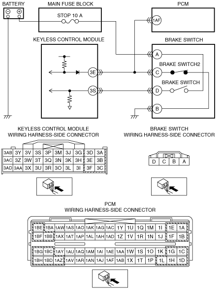
― Brake switch terminal C—PCM terminal 1AF
― Brake switch terminal C—Keyless control module terminal 3E
― Brake switch terminal D—Keyless control module terminal 3S
• Is there continuity?
|
Yes
|
Go to the next step.
|
|
No
|
Repair or replace the wiring harness for a possible open circuit, then go to Step 10.
|
|
9
|
INSPECT PCM
• Make sure to reconnect the disconnected connectors.
• Reconnect the negative battery cable.
• Measure the voltage at the PCM terminal 1AF (wiring harness-side).
|
Yes
|
Replace the brake switch, then go to the next step.
-
Caution
-
• Inspect the brake switch with it installed to the brake pedal, otherwise the brake switch may not operate normally. If the brake switch is removed from the brake pedal, replace the brake switch with a new one.
|
|
No
|
Replace the PCM, then go to the next step.
|
|
10
|
VERIFY TROUBLESHOOTING COMPLETED
• Make sure to reconnect the disconnected connectors.
• Reconnect the negative battery cable.
• Clear the DTC from the keyless control module using the M-MDS.
• Perform the advanced keyless entry and push button start system DTC inspection using the M-MDS.
• Is the same DTC present?
|
Yes
|
Repeat the inspection from Step 1.
If the malfunction recurs, replace the keyless control module, then go to the next step.
|
|
No
|
Go to the next step.
|
|
11
|
VERIFY THAT NO OTHER DTCs ARE PRESENT
• Are any DTCs present?
|
Yes
|
Go to the applicable DTC inspection.
|
|
No
|
DTC troubleshooting completed.
|