|
1
|
VERIFICATION BEFORE SERVICING
• Are any DTCs, except the following, displayed?
-
― U0001:88
― U0073:00
|
Yes
|
|
|
No
|
Go to the next step.
|
|
2
|
INSPECTION OF CONTROL MODULE CONNECTOR OUTPUTTING DTCs
• Inspect the terminal condition of the control module connector outputting DTCs and the mid-connector.
• Are the connector terminals normal without damage, deformation, corrosion, or disconnection?
|
Yes
|
Go to the next step.
|
|
No
|
Repair or replace the connector, then go to Step 9.
|
|
3
|
INSPECTION OF POWER SUPPLY OF CONTROL MODULE OUTPUTTING DTCs
• Refer to the terminal voltage table of the control module outputting DTCs or use the PID/data monitoring function to inspect the terminal voltage and fuse condition.
• Is the power supply voltage normal?
|
Yes
|
Go to the next step.
|
|
No
|
Repair or replace the connector, then go to Step 9.
|
|
4
|
INSPECTION OF BODY GROUND CONDITION OF CONTROL MODULE OUTPUTTING DTCs
• Inspect the body ground wires and ground point of the control module outputting DTCs.
• Are the ground and ground point normal?
|
Yes
|
Go to the next step.
|
|
No
|
Repair or replace the connector, then go to Step 9.
|
|
5
|
CAN SYSTEM RELATED WIRING HARNESS INSPECTION
• CAN system related wiring harness inspection:
-
― Short to ground
― Short to power supply
― Short between twisted pair wiring harness
― Open circuit
• Is the wiring harness normal?
|
Yes
|
Go to the next step.
|
|
No
|
Repair or replace the connector, then go to Step 9.
|
|
6
|
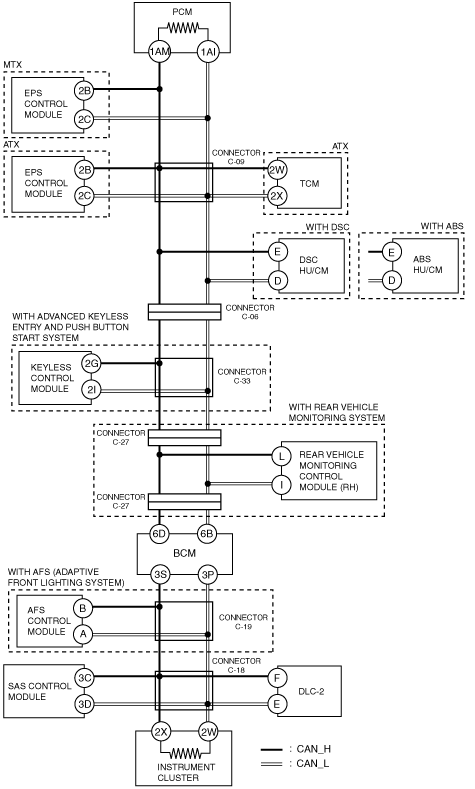
INSPECT PCM
• Disconnect the PCM connector.
• Measure the resistance between the following PCM connector terminals:
-
― Between terminal 1AM and terminal 1AI (part side)
• Is the resistance 118-130 ohms?
|
Yes
|
Go to the next step.
|
|
No
|
Replace the PCM, then go to Step 9.
|
|
7
|
INSPECT INSTRUMENT CLUSTER
• Disconnect the instrument cluster connector.
• Measure the resistance between the following instrument cluster connector terminals:
-
― Between terminal 2X and terminal 2W (part side)
• Is the resistance 118-130 ohms?
|
Yes
|
Go to the next step.
|
|
No
|
Replace the instrument cluster, then go to Step 9.
|
|
8
|
CAN RELATED MODULE VERIFICATION
• Remove only one of the CAN-related modules.
• Clear DTCs using the M-MDS.
• Inspect the DTCs of all modules using the M-MDS.
• Are DTCs U0001:88, U0073:00 displayed?
|
Yes
|
Reinstall the removed module, remove another module and perform the same inspection. Inspect all of the CAN-related modules using the same procedure. After inspecting all of the modules, go to the next step.
|
|
No
|
Replace the removed module.
|
|
9
|
AFTER REPAIR VERIFICATION
• Connect all of the modules.
• Clear DTCs using the M-MDS.
• Inspect the DTCs using the M-MDS.
• Are DTCs displayed?
|
Yes
|
Perform the CAN system on-board diagnosis again according to the troubleshooting procedure
|
|
No
|
DTC troubleshooting completed.
|