|
1
|
• Retrieve the advanced keyless entry and push button start system DTC using the M-MDS.
• Are there DTC displayed?
|
Yes
|
Go to the applicable DTC troubleshooting procedures.
|
|
No
|
Go to the next step.
|
|
2
|
• Did the customer attempt to operate each front doors and liftgate/trunk lid using the touch sensor?
|
Yes
|
Go to the next step.
|
|
No
|
• Inspect the advanced keyless system operations using the request switch.
• If the advanced keyless system is inoperative, then go to the next step.
|
|
3
|
• Prepare the followings:
-
― All doors and trunk lid/liftgate closed
― Switch the ignition to off. (without ACC and IG ON position)
― Make sure that the advanced key is within the advanced keyless system operative area (within 80 cm {2.6 ft} from front door)
― The auxiliary key is inserted in the ignition switch.
• Does the advanced keyless system operate properly?
|
Yes
|
The system is normal.
Explain the advanced keyless system operation.
|
|
No
|
Go to the next step.
|
|
4
|
• Confirm the problem using another electrical key.
• Is the same problem remained?
|
Yes
|
Go to Step 6.
|
|
No
|
Go to the next step.
|
|
5
|
• Lock and unlock operation using advanced key button that has problem.
• Are the lock and unlock operations properly?
|
Yes
|
Replace the electrical key.
(internal malfunction)
|
|
No
|
Replace the electrical key battery, then go to Step 29.
|
|
6
|
• Verify that the trouble occurred condition.
• Is the problem occurred lock operation only?
|
Yes
|
Go to Step 8
|
|
No
|
Go to the next step.
|
|
7
|
• Verify that the trouble occurred condition.
• Is the problem occurred unlock operation only?
|
Yes
|
Go to Step 15.
|
|
No
|
Go to Step 21.
|
|
8
|
• Monitor the following keyless control module PIDs using the M-MDS.
-
― REQ_SW_R (RF lock request switch)
― REQ_SW_L (LF lock request switch)
• Are PIDs indicated properly?
Specification
-
Switch pushed: ON
Other: OFF
|
Yes
|
Go to the next step.(WGN)
Go to Step 13.(5HB, 4SD)
|
|
No
|
Go to Step 10.
|
|
9
|
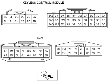
• Measure the voltage at the keyless control module terminal 3D.
• Is the voltage normal?
Specification
-
Liftgate request switch is pushed: 1.0 V or less
Others: B+
|
Yes
|
Go to Step 13.
|
|
No
|
Go to the next step.
|
|
10
|
• Switch the ignition to off.
• Disconnect the keyless control module (30-pin) door handle (incorrect PID value at Step 8 and request switch (liftgate)(incorrect voltage at Step 9) connectors.
• Verify continuity between suspect door handle harness-side connector terminal D and GND.
• Verify continuity between request switch (liftgate) terminal B and GND.
• Is there continuity?
|
Yes
|
• Repair or replace wiring harness for short to GND circuit.
• Then go to Step 29.
|
|
No
|
Go to the next step.
|
|
11
|
• Keyless control module and handle switch and request switch (liftgate) disconnected.
• Verify continuity between door handle connector terminal D and following keyless control module terminal at each harness-side connector.
-
― Terminal 3U for right-side door handle
― Terminal 3X for left-side door handle
• Verify continuity between request switch (liftgate) terminal B and keyless control module terminal 3D.(WGN)
• Is there continuity?
|
Yes
|
Go to the next step.
|
|
No
|
• Repair or replace for open circuit.
• Then go to Step 29.
|
|
12
|
• Handle switch disconnected.
• Verify continuity between suspect door handle harness-side connector terminal A and GND.
• Is there continuity?
|
Yes
|
• Replace suspect door handle.
• Then go to Step 29.
|
|
No
|
• Repair or replace wiring harness for open circuit.
• Re-tighten the ground wire as necessary.
• Then go to Step 29.
|
|
13
|
• Monitor the following BCM PIDs using the M-MDS.
-
― TR/LG—SW (Liftgate latch switch)
― DRSW—RR (Right rear door latch switch)
― DRSW—LR (Left rear door latch switch)
― DRSW—P (Passenger’s door latch switch)
― DRSW—D (Driver’s door latch switch)
• Are PIDs indicated properly?
|
Yes
|
• Go to the next step.
|
|
No
|
• Inspect suspect door latch switch and wiring harness.
• Repair or replace as necessary.
• Then go to Step 29.
|
|
14
|
• Measure the voltage at the BCM terminals 7I and 7M while the lock door using the lock request switch.
-
― Lock all doors with the advanced key: 1.0 V or less→B+→1.0 V or less (terminal 7I)
― Double lock all doors with the advanced key: 1.0 V or less→B+→1.0 V or less (terminal 7M)
• Is the voltage as above?
|
Yes
|
• Inspect and repair the wiring harness between the BCM and the door lock actuator.
• Inspect for door lock actuator.
• Then go to Step 29.
|
|
No
|
• Then go to Step 29.
|
|
15
|
• Measure the voltage at the BCM terminals 7K and 7M while the unlock door using the unlock request switch.
-
― Unlock all doors and liftgate with the advanced key:1.0 V or less → B+→ 1.0 V or less
• Is the voltage as above?
|
Yes
|
• Inspect and repair the wiring harness between the BCM and the door lock actuator.
• Inspect for door lock actuator.
• Then go to Step 29.
|
|
No
|
Go to the next Step.
|
|
16
|
• Monitor the following keyless control module PIDs using the M-MDS.
-
― LOCK_SW_D (door lock link switch)
• Are PIDs indicated properly?
Specification
-
Driver's door: LOCK: Lock
Driver's door: UNLOCK: Unlock
|
Yes
|
Go to the next Step.
|
|
No
|
Inspect the door lock link switch, replace it as necessary.
• Door lock link switch
• Verify continuity between door lock link switch connector terminal J and keyless control module terminal 3P at each harness-side connector
|
|
17
|
• Switch the ignition to off.
• Disconnect the door handle connector of the malfunctioning door from the keyless control module (30-pin) connector.
• Verify continuity between suspect door handle harness-side connector terminal C and GND.
• Is there continuity?
|
Yes
|
• Repair or replace wiring harness for short to GND circuit.
• Then go to Step 29.
|
|
No
|
Go to the next step.
|
|
18
|
• Keyless control module and handle switch disconnected.
• Verify continuity between door handle connector terminal C and following keyless control module terminal at each harness-side connector.
-
― Terminal 3H for right-side door handle
― Terminal 3Q for left-side door handle
• Is there continuity?
|
Yes
|
Go to the next step.
|
|
No
|
• Repair or replace for open circuit.
• Then go to Step 29.
|
|
19
|
• Handle switch disconnected.
• Verify continuity between suspect door handle harness-side connector terminal F and GND.
• Is there continuity?
|
Yes
|
Go to the next step.
|
|
No
|
• Repair or replace wiring harness for open circuit.
• Re-tighten the ground wire as necessary.
• Then go to Step 29.
|
|
20
|
• Switch the outer handle of the malfunctioning door with the outer handle of the door on the opposite side (or a normal outer handle): Connecting only the connectors is sufficient.
• Verify the malfunction symptom.
• Does the malfunction recur on the door on the opposite side? (Is the source of the malfunction determined?)
|
Yes
|
• Replace suspect door handle.
• Then go to Step 29.
|
|
No
|
• Then go to Step 29.
|
|
21
|
• Verify that the liftgate/trunk lid open function.
• Is the liftgate/trunk lid open with liftgate/trunk lid opener switch?
|
Yes
|
Go to Step 25.
|
|
No
|
Go to the next step.
|
|
22
|
• Measure the voltage at the keyless control module terminal 3G.
• Is the voltage normal?
Specification
-
Liftgate/trunk lid opener switch is pushed: 3.0 VOthers: 4.7 V
|
Yes
|
Go to Step 27.
|
|
No
|
Go to the next step.
|
|
23
|
• Switch the ignition to off.
• Disconnect the keyless control module (30-pin) and liftgate/trunk lid opener switch connectors.
• Verify continuity between liftgate/trunk lid opener switch harness-side connector terminal A and GND.
• Is there continuity?
|
Yes
|
• Repair or replace wiring harness for short to GND circuit.
• Then go to Step 29.
|
|
No
|
Go to the next step.
|
|
24
|
• Keyless control module and opener switch disconnected.
• Verify continuity between liftgate/trunk lid opener switch terminal A and following keyless control module terminal 3G at each harness-side connector.
• Is there continuity?
|
Yes
|
• Inspect the liftgate/trunk lid opener switch, replace it as necessary.
-
― If normal, inspect following parts and repair or replace as necessary.
-
• Liftgate latch and actuator
• Trunk lid latch and actuator
• Open or short circuit in wiring harness between liftgate/trunk lid latch and BCM.
• Open or short circuit in wiring harness between liftgate/trunk lid actuator and BCM.
• Then go to Step 29.
|
|
No
|
• Repair or replace for open circuit.
• Then go to Step 29.
|
|
25
|
• Switch the ignition to off.
• Disconnect the keyless control module and suspect exterior keyless antenna connector.
• Verify continuity between following suspect keyless antenna harness-side connector terminal and GND.
-
― Door handle terminal B (exterior LH/RH)
― Door handle terminal E (exterior LH/RH)
― Keyless antenna (exterior rear) terminal C
― Keyless antenna (exterior rear) terminal D
• Is there continuity?
|
Yes
|
Repair or replace for short to GND, then go to Step 29.
|
|
No
|
Go to the next step.
|
|
26
|
• Replace the suspect exterior keyless antenna to other keyless antenna (interior rear, other side door handle) temporarily.
-
― If the symptom is occurring while the front outer handle switch operates, replace to the other side front outer handle with connector is connected.
― If the symptom is occurring while the liftgate request switch operates, replace to the keyless antenna (interior rear) with connector is connected.
• Verify the malfunction symptom.
• Is the symptom solved?
|
Yes
|
Replace the suspect exterior keyless antenna, then go to Step 29.
|
|
No
|
Go to the next step.
|
|
27
|
• Switch the ignition to off.
• Disconnect the BCM (16-pin) and keyless control module (12-pin) connectors.
• Verify continuity between keyless control module harness-side connector terminal 2F and GND.
• Is there continuity?
|
Yes
|
• Repair or replace wiring harness for short to GND circuit.
• Then go to Step 29.
|
|
No
|
Go to the next step.
|
|
28
|
• BCM (16-pin) and keyless control module (12-pin) connectors disconnected.
• Verify continuity between BCM connector terminal 6J and keyless control module terminal 2F at each harness-side connector.
• Is there continuity?
|
Yes
|
• Replace the keyless control module.
• Then go to the next step.
|
|
No
|
• Repair or replace wiring harness for open circuit.
• Then go to the next step.
|
|
29
|
• Does the keyless entry system operate properly?
|
Yes
|
Troubleshooting completed. Explain repairs to the customers.
|
|
No
|
Re-inspect the malfunction symptoms, then repeat form Step 1 if malfunction recurs.
|