POWER WINDOW MAIN SWITCH INSPECTION
id091200002100
Auto-open/close Function For All Windows
1. Switch the ignition to ON.
2. Verify that the door glass (driver’s side) can be operated for approx. 43 s after the ignition is switched off.
-
• If the door glass (driver’s side) cannot be operated for approx. 43 s after the ignition is switched off, or if the door glass (driver’s side) can still be operated after approx. 43 s, replace the power window main switch.
3. Disconnect the negative battery cable.
4. Remove the inner garnish. (driver's side)(See INNER GARNISH REMOVAL/INSTALLATION.)
5. Remove the front door trim. (driver's side)(See FRONT DOOR TRIM REMOVAL/INSTALLATION.)
6. Remove the power window main switch. (driver's side)(See FRONT DOOR TRIM DISASSEMBLY/ASSEMBLY.)
7. Connect the power window main switch connector.
8. Connect the negative battery cable.
9. Measure the voltage at each terminal.
-
• If the voltage is not as specified in the terminal voltage table, inspect the parts under Inspection item (s) and related wiring harnesses.
-
― If the system does not work normally even though the inspection items or related wiring harnesses do not have any malfunction, replace the power window main switch.
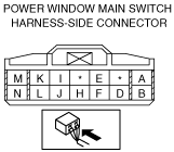
Terminal voltage table (reference)
|
Terminal
|
Signal name
|
Connected to
|
Measurement condition
|
Voltage (V)
|
Inspection item (s)
|
|
A
|
Driver’s side window close signal
|
Power window motor (driver’s side)
|
Door glass (driver’s side) closing
|
B+
|
• Power window motor (driver’s side)
• Related wiring harness
|
|
Other
|
1.0 or less
|
|
B
|
GND
|
Body ground
|
Under any condition
|
1.0 or less
|
• Related wiring harness
|
|
C
|
—
|
—
|
—
|
—
|
—
|
|
D
|
Sensor ground
|
Power window motor (driver’s side)
|
Under any condition
|
1.0 or less
|
• Power window motor (driver’s side)
• Related wiring harness
|
|
E
|
Sensor power supply
|
Power window motor (driver’s side)
|
Switch the ignition to ON
|
approx. 10.0
|
• Power window motor (driver’s side)
• Related wiring harness
|
|
Switch the ignition to OFF
|
1.0 or less
|
|
F
|
IG1
|
P/W 15 A fuse
|
Switch the ignition to ON
|
B+
|
• P/W 15 A fuse
• Related wiring harness
|
|
Switch the ignition to OFF
|
1.0 or less
|
|
G
|
—
|
—
|
—
|
—
|
—
|
|
H
|
Pulse 1
|
Power window motor (driver’s side)
|
Door glass (driver’s side) operating
|
Alternates between 1.0 or less and 5
|
• Power window motor (driver’s side)
• Related wiring harness
|
|
I
|
Communication
|
Power window subswitch
|
Because this terminal is for communication, good/no good judgment by terminal voltage is not possible
|
• Power window subswitch
• Related wiring harness
|
|
J
|
Pulse 2
|
Power window motor (driver’s side)
|
Door glass (driver’s side) operating
|
Alternates between 1.0 or less and 5
|
• Power window motor (driver’s side)
• Related wiring harness
|
|
K
|
Door open/close signal
|
BCM
|
Because this terminal is for communication, good/no good judgment by terminal voltage is not possible
|
• Power window motor (driver’s side)
• Related wiring harness
|
|
L
|
Power-cut signal
|
Power window subswitch
|
Switch the ignition to ON and power-cut switch at LOCK
|
1.0 or less
|
• Power window subswitch
• Related wiring harness
|
|
Switch the ignition to ON and power-cut switch at UNLOCK
|
approx. 7.0
|
|
M
|
Driver’s side window open signal
|
Power window motor (driver’s side)
|
Door glass (driver’s side) opening
|
B+
|
• Power window motor (driver’s side)
• Related wiring harness
|
|
Other
|
1.0 or less
|
|
N
|
Power supply
|
P/W 30 A fuse
|
Under any condition
|
B+
|
• P/W 30 A fuse
• Related wiring harness
|
Auto-open/close Function for Driver-side
1. Switch the ignition to ON.
2. Verify that the door glass (driver’s side) can be operated for approx. 43 s after the ignition is switched off.
-
• If the door glass (driver’s side) cannot be operated for approx. 43 s after the ignition is switched off, or if the door glass (driver’s side) can still be operated after approx. 43 s, replace the power window main switch.
3. Disconnect the negative battery cable.
4. Remove the inner garnish. (driver's side) (See INNER GARNISH REMOVAL/INSTALLATION.)
5. Remove the front door trim. (driver's side) (See FRONT DOOR TRIM REMOVAL/INSTALLATION.)
6. Remove the power window main switch. (driver's side) (See FRONT DOOR TRIM DISASSEMBLY/ASSEMBLY.)
7. Connect the power window main switch connector.
8. Connect the negative battery cable.
9. Measure the voltage at each terminal.
-
• If the voltage is not as specified in the terminal voltage table, inspect the parts under Inspection item (s) and related wiring harnesses.
-
― If the system does not work normally even though the inspection items or related wiring harnesses do not have any malfunction, replace the power window main switch.
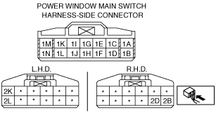
Terminal voltage table (reference)
|
Terminal
|
Signal name
|
Connected to
|
Measurement condition
|
Voltage (V)
|
Inspection item (s)
|
|
1A
|
Sensor ground
|
Power window motor (driver’s side)
|
Under any condition
|
1.0 or less
|
• Power window motor (driver’s side)
• Related wiring harness
|
|
1B
|
GND
|
Body ground
|
Under any condition
|
1.0 or less
|
• Related wiring harness
|
|
1C
|
Rear right side window close signal
|
Power window motor (rear right side)
|
Door glass (rear right side) closing
|
B+
|
• Power window motor (rear right side)
• Related wiring harness
|
|
Other
|
1.0 or less
|
|
1D
|
Pulse 1
|
Power window motor (driver’s side)
|
Door glass (driver’s side) operating
|
Alternates between 1.0 or less and 5
|
• Power window motor (driver’s side)
• Related wiring harness
|
|
1E
|
Rear right side window open signal
|
Power window motor (rear right side)
|
Door glass (rear right side) opening
|
B+
|
• Power window motor (rear right side)
• Related wiring harness
|
|
Other
|
1.0 or less
|
|
1F
|
Sensor power supply
|
Power window motor (driver’s side)
|
Switch the ignition to ON
|
approx. 10.0
|
• Power window motor (driver’s side)
• Related wiring harness
|
|
Switch the ignition to OFF
|
1.0 or less
|
|
1G
|
Rear left side window open signal
|
Power window motor (rear left side)
|
Door glass (rear left side) opening
|
B+
|
• Power window motor (rear left side)
• Related wiring harness
|
|
Other
|
1.0 or less
|
|
1H
|
Pulse 2
|
Power window motor (driver’s side)
|
Door glass (driver’s side) operating
|
Alternates between 1.0 or less and 5
|
• Power window motor (driver’s side)
• Related wiring harness
|
|
1I
|
Rear left side window close signal
|
Power window motor (rear left side)
|
Door glass (rear left side) closing
|
B+
|
• Power window motor (rear left side)
• Related wiring harness
|
|
Other
|
1.0 or less
|
|
1J
|
Driver’s side window close signal
|
Power window motor (driver’s side)
|
Door glass (driver’s side) closing
|
B+
|
• Power window motor (driver’s side)
• Related wiring harness
|
|
Other
|
1.0 or less
|
|
1K
|
Door open/close signal
|
BCM
|
Because this terminal is for communication, good/no good judgment by terminal voltage is not possible
|
• Power window motor (driver’s side)
• Related wiring harness
|
|
1L
|
Driver’s side window open signal
|
Power window motor (driver’s side)
|
Door glass (driver’s side) opening
|
B+
|
• Power window motor (driver’s side)
• Related wiring harness
|
|
Other
|
1.0 or less
|
|
1M
|
IG1
|
P/W IG 30 A fuse
|
Switch the ignition to ON
|
B+
|
• P/W IG 30 A fuse
• Related wiring harness
|
|
Switch the ignition to OFF
|
1.0 or less
|
|
1N
|
Power supply
|
P/W 30 A fuse
|
Under any condition
|
B+
|
• P/W 30 A fuse
• Related wiring harness
|
L.H.D.
|
Terminal
|
Signal name
|
Connected to
|
Measurement condition
|
Voltage (V)
|
Inspection item (s)
|
|
2K
|
Passenger’s side window open signal
|
Power window motor (passenger’s side)
|
Door glass (passenger’s side) opening
|
B+
|
• Power window motor (passenger’s side)
• Related wiring harness
|
|
Other
|
1.0 or less
|
|
2L
|
Passenger’s side window close signal
|
Power window motor (passenger’s side)
|
Door glass (passenger’s side) closing
|
B+
|
• Power window motor (passenger’s side)
• Related wiring harness
|
|
Other
|
1.0 or less
|
R.H.D.
|
Terminal
|
Signal name
|
Connected to
|
Measurement condition
|
Voltage (V)
|
Inspection item (s)
|
|
2B
|
Passenger’s side window close signal
|
Power window motor (passenger’s side)
|
Door glass (passenger’s side) closing
|
B+
|
• Power window motor (passenger’s side)
• Related wiring harness
|
|
Other
|
1.0 or less
|
|
2D
|
Passenger’s side window open signal
|
Power window motor (passenger’s side)
|
Door glass (passenger’s side) opening
|
B+
|
• Power window motor (passenger’s side)
• Related wiring harness
|
|
Other
|
1.0 or less
|
 am6zzw00006632