 |
am6zzw00006192
REAR VEHICLE MONITORING CONTROL MODULE INSPECTION
id092200146100
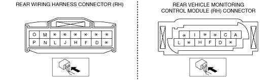
Rear vehicle monitoring control module (RH)
1. Disconnect the negative battery cable.
2. Peel off the seaming welt.
3. Remove the following parts: (4SD)
4. Remove the following parts: (5HB)
5. Remove the following parts: (Wagon)
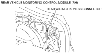
6. Measure the rear vehicle monitoring control module terminal voltage using the rear wiring harness connector in the position shown in the figure.
am6zzw00006192
|
Terminal Voltage Table (Reference)
Rear vehicle monitoring control module (RH)
am6zzw00005050
|
|
Rear wiring harness terminal |
Rear vehicle monitoring CM (RH) terminal |
Signal |
Connected to |
Measurement condition |
Voltage (V) |
Inspection item(s) |
|
|---|---|---|---|---|---|---|---|
|
A
|
—
|
—
|
—
|
—
|
—
|
—
|
|
|
B
|
—
|
—
|
—
|
—
|
—
|
—
|
|
|
C
|
—
|
—
|
—
|
—
|
—
|
—
|
|
|
D
|
D
|
RVM switch signal
|
RVM switch
|
Switch the ignition to ON
|
RVM switch pressed
|
1.0 or less
|
• RVM switch
• Related wiring harness
|
|
RVM switch not pressed
|
+B
|
||||||
|
E
|
—
|
—
|
—
|
—
|
—
|
—
|
|
|
F
|
F
|
Power supply
|
Fuse
|
Switch the ignition to ON
|
+B
|
• Fuse
• Related wiring harness
|
|
|
Switch the ignition to off
|
1.0 or less
|
||||||
|
G
|
—
|
—
|
—
|
—
|
—
|
—
|
|
|
H
|
H
|
Ground
|
Body ground
|
Under any condition
|
1.0 or less
|
• Related wiring harness
|
|
|
I
|
—
|
—
|
—
|
—
|
—
|
—
|
|
|
J
|
C
|
CAN2_H
|
Rear vehicle monitoring control module (LH)
|
Terminal used for communication therefore determination based on terminal voltage is not possible.
|
|||
|
K
|
—
|
—
|
—
|
—
|
—
|
—
|
|
|
L
|
A
|
CAN2_L
|
Rear vehicle monitoring control module (LH)
|
Terminal used for communication therefore determination based on terminal voltage is not possible.
|
|||
|
M
|
L
|
CAN_H
|
CAN system related module
|
Terminal used for communication therefore determination based on terminal voltage is not possible.
|
|||
|
N
|
L
|
CAN_H
|
CAN system related module
|
Terminal used for communication therefore determination based on terminal voltage is not possible.
|
|||
|
O
|
I
|
CAN_L
|
CAN system related module
|
Terminal used for communication therefore determination based on terminal voltage is not possible.
|
|||
|
P
|
I
|
CAN_L
|
CAN system related module
|
Terminal used for communication therefore determination based on terminal voltage is not possible.
|
|||
Rear vehicle monitoring control module (LH)
1. Peel off the seaming welt.
2. Remove the trunk mat.
3. Remove the trunk board.
4. Remove the sub-trunk. (Wagon)
5. Remove the trunk end trim. (See TRUNK END TRIM REMOVAL/INSTALLATION.)
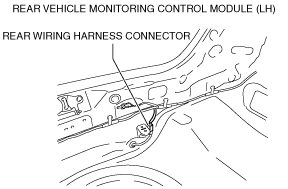
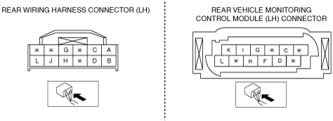
6. Measure the rear vehicle monitoring control module terminal voltage using the rear wiring harness connector in the position shown in the figure.
am6zzw00006193
|
Rear vehicle monitoring control module (LH)
am6zzw00005452
|
|
Rear wiring harness terminal |
Rear vehicle monitoring CM (LH) terminal |
Signal |
Connected to |
Measurement condition |
Voltage (V) |
Inspection item(s) |
|
|---|---|---|---|---|---|---|---|
|
A
|
K
|
RVM warning indicator light signal (LH)
|
RVM warning indicator light (LH)
|
Switch the ignition to ON
|
LED off
|
1.0 or less
|
• RVM warning indicator light LED (LH)
• Related wiring harness
|
|
LED on
|
3.0—5.0
|
||||||
|
B
|
G
|
RVM warning indicator light ground signal (LH)
|
RVM warning indicator light (LH)
|
Under any condition
|
1.0 or less
|
• RVM warning indicator light LED (LH)
• Related wiring harness
|
|
|
C
|
D
|
RVM warning indicator light signal (RH)
|
RVM warning indicator light (RH)
|
Switch the ignition to ON
|
LED off
|
1.0 or less
|
• RVM warning indicator light LED (RH)
• Related wiring harness
|
|
LED on
|
3.0—5.0
|
||||||
|
D
|
C
|
RVM warning indicator light ground signal (RH)
|
RVM warning indicator light (RH)
|
Under any condition
|
1.0 or less
|
• RVM warning indicator light LED (RH)
• Related wiring harness
|
|
|
E
|
—
|
—
|
—
|
—
|
—
|
—
|
|
|
F
|
—
|
—
|
—
|
—
|
—
|
—
|
|
|
G
|
F
|
Power supply
|
Fuse
|
Switch the ignition to ON
|
+B
|
• Fuse
• Related wiring harness
|
|
|
Switch the ignition to off
|
1.0 or less
|
||||||
|
H
|
H
|
Ground
|
Body ground
|
Under any condition
|
1.0 or less
|
• Related wiring harness
|
|
|
I
|
—
|
—
|
—
|
—
|
—
|
—
|
|
|
J
|
L
|
CAN2_H
|
Rear vehicle monitoring control module (RH)
|
Terminal used for communication therefore determination based on terminal voltage is not possible.
|
|||
|
K
|
—
|
—
|
—
|
—
|
—
|
—
|
|
|
L
|
I
|
CAN2_L
|
Rear vehicle monitoring control module (RH)
|
Terminal used for communication therefore determination based on terminal voltage is not possible.
|
|||